edakit documentation

guitar – reference circuit

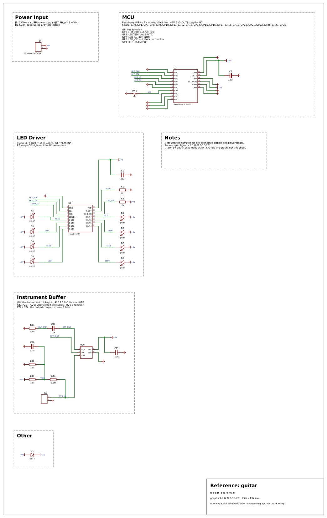
An instrument buffer: the jack J20's tip on GTR_IN (a pickup that wants at least 1 MΩ), 2.2 MΩ to the reference VREF (10 kΩ / 10 kΩ from +5V, 22 µF), U20 an op-amp follower on +5V with 100 nF; its output coupled through C22 1 µF (film) onto BUF_OUT with R24 100 kΩ to ground – an AC run expects the follower flat at 1 kHz and the coupling's corner, 1.6 Hz, below 10 Hz.

Why: Every pedal starts with a buffer at the instrument input. It holds the pickup's load, a reference inside the op-amp's input range, a bypass that keeps the signal's level, and the corners of the signal path in an AC run.

Domains on: core guitar · SVG

Reference: guitar led-bar · board main graph v1.0 (2026-10-25) · 276 x 437 mm drawn by edakit schematic draw – change the graph, not this drawing Power Input J1: 5 V from a USB power supply (JST PH, pin 1 = VIN) D1 SS34: reverse-polarity protection MCU Raspberry Pi Pico 2 module; VSYS from +5V, 3V3(OUT) supplies U2 Spare: GP0, GP1, GP7, GP8, GP9, GP10, GP11, GP12, GP13, GP14, GP15, GP16, GP17, GP18, GP19, GP20, GP21, GP22, GP26, GP27, GP28 GP net function GP2 LED_CLK out, SPI SCK GP3 LED_SDI out, SPI TX GP4 LED_LE out, latch GP5 LED_OE out, PWM, active low GP6 BTN in, pull-up LED Driver TLC5916: I_OUT = 15 x 1.26 V / R1 = 9.45 mA R2 keeps OE high until the firmware runs Notes Nets with the same name are connected (labels and power flags). Source: graph.json v1.0 (2026-10-25) Drawn by edakit schematic draw – change the graph, not this sheet. Instrument Buffer J20: the instrument (pickup) in, R20 2.2 MΩ bias to VREF R21/R22 + C20: VREF at half the supply; U20 a follower C22 / R24: the output coupled, corner 1.6 Hz Other LED_CLK LED_CLK LED_SDI LED_SDI LED_LE LED_LE LED_OE LED_OE BTN LED0 LED1 LED2 LED3 LED4 LED5 LED6 LED7 REXT GTR_OUT GTR_OUT BUF_OUT GTR_IN VREF VIN 3V3 +5V +5V +5V +5V +5V +5V +5V +5V +5V 3V3 3V3 +5V +5V +5V VIN 1 2 J1 B2B-PH-K-S(LF)(SN) GND 3 GP2 4 GP3 5 GP4 6 GP5 7 GND 8 GP6 9 GND 13 GND 18 GND 23 GND 42 VSYS 39 GND 38 3V3(OUT) 36 AGND 33 GND 28 U1 Raspberry Pi Pico 2 SW1 C2 22uF GND 1 SDI 2 CLK 3 LE(ED1) 4 OUT0 5 OUT1 6 OUT2 7 OUT3 8 VDD 16 R-EXT 15 OE(ED2) 13 OUT7 12 OUT6 11 OUT5 10 OUT4 9 U2 TLC5916IDR D2 green D3 green D4 green D5 green D6 green D7 green D8 green D9 green R2 10k R1 2k C1 100nF OUT 1 -IN 2 +IN 3 VCC 5 GND 4 U20 C22 1uF R24 100k 1 2 J20 R20 2.2M R21 10k R22 10k C20 22uF C21 100nF D1 SS34
Seeded faultCodes it raises
a bias of 470 kΩREQ.value
a reference above the inputs' rangeLIM.range
a bypass switch to an output at 0 VREQ.value
a coupling capacitor ten times smallerSIM.response