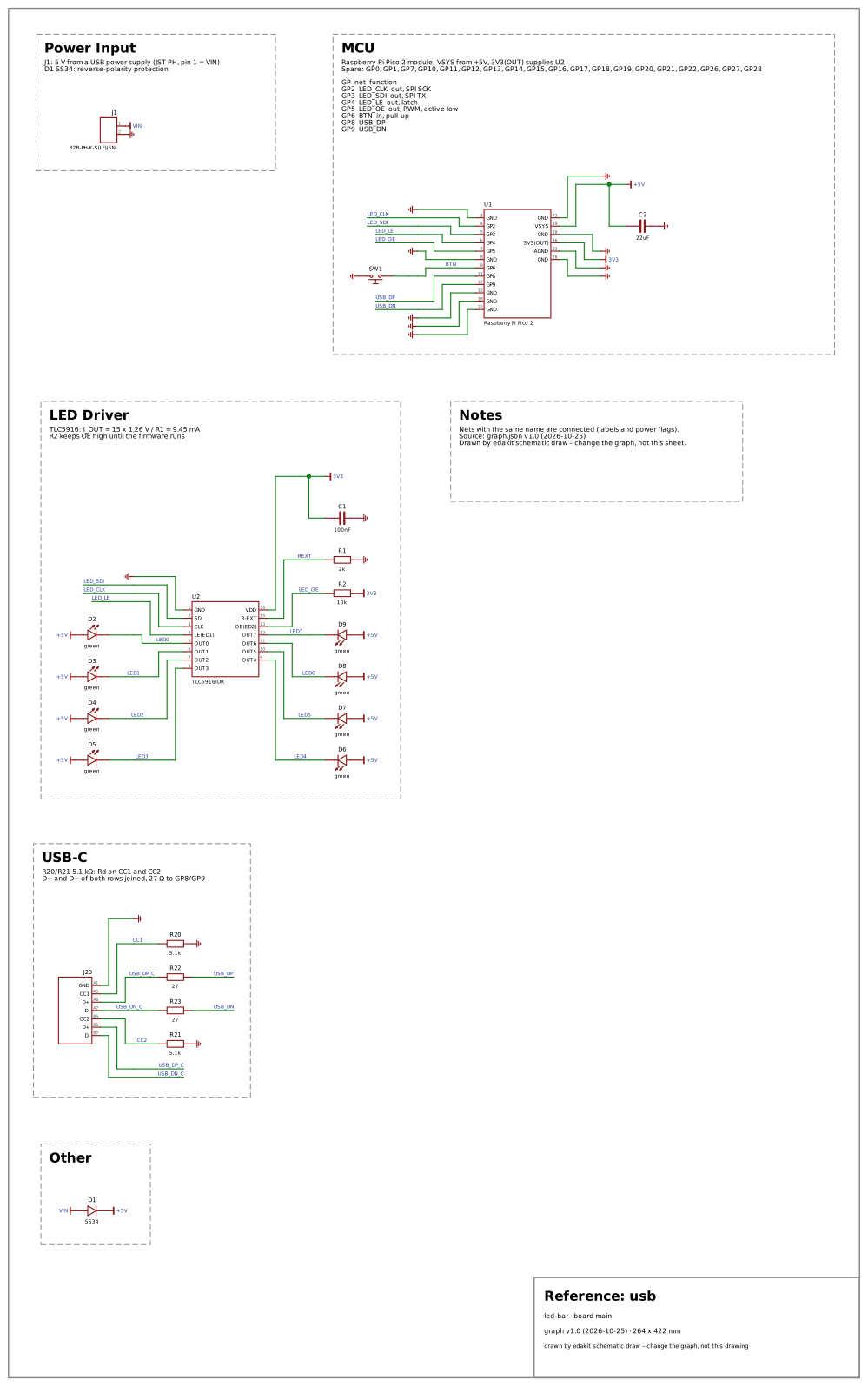
J20, a USB-C receptacle for data: 5.1 kΩ from each CC pin to GND, D+ and D− of both rows joined to GP8 and GP9 through 27 Ω.
Why: A USB-C receptacle for data is on most new boards. It holds Rd on both CC pins and D+ and D- of both rows – a board that misses one works only one way round.
Domains on: core usb · SVG
Reference: usb
led-bar · board main
graph v1.0 (2026-10-25) · 264 x 422 mm
drawn by edakit schematic draw – change the graph, not this drawing
Power Input
J1: 5 V from a USB power supply (JST PH, pin 1 = VIN)
D1 SS34: reverse-polarity protection
MCU
Raspberry Pi Pico 2 module; VSYS from +5V, 3V3(OUT) supplies U2
Spare: GP0, GP1, GP7, GP10, GP11, GP12, GP13, GP14, GP15, GP16, GP17, GP18, GP19, GP20, GP21, GP22, GP26, GP27, GP28
GP net function
GP2 LED_CLK out, SPI SCK
GP3 LED_SDI out, SPI TX
GP4 LED_LE out, latch
GP5 LED_OE out, PWM, active low
GP6 BTN in, pull-up
GP8 USB_DP
GP9 USB_DN
LED Driver
TLC5916: I_OUT = 15 x 1.26 V / R1 = 9.45 mA
R2 keeps OE high until the firmware runs
Notes
Nets with the same name are connected (labels and power flags).
Source: graph.json v1.0 (2026-10-25)
Drawn by edakit schematic draw – change the graph, not this sheet.
USB-C
R20/R21 5.1 kΩ: Rd on CC1 and CC2
D+ and D− of both rows joined, 27 Ω to GP8/GP9
Other
LED_CLK
LED_CLK
LED_SDI
LED_SDI
LED_LE
LED_LE
LED_OE
LED_OE
BTN
USB_DP
USB_DP
USB_DN
USB_DN
LED0
LED1
LED2
LED3
LED4
LED5
LED6
LED7
REXT
USB_DN_C
USB_DN_C
USB_DP_C
USB_DP_C
CC2
CC1
VIN
3V3
+5V
+5V
+5V
+5V
+5V
+5V
+5V
+5V
+5V
3V3
3V3
+5V
VIN
1
2
J1
B2B-PH-K-S(LF)(SN)
GND
3
GP2
4
GP3
5
GP4
6
GP5
7
GND
8
GP6
9
GP8
11
GP9
12
GND
13
GND
18
GND
23
GND
42
VSYS
39
GND
38
3V3(OUT)
36
AGND
33
GND
28
U1
Raspberry Pi Pico 2
SW1
C2
22uF
GND
1
SDI
2
CLK
3
LE(ED1)
4
OUT0
5
OUT1
6
OUT2
7
OUT3
8
VDD
16
R-EXT
15
OE(ED2)
13
OUT7
12
OUT6
11
OUT5
10
OUT4
9
U2
TLC5916IDR
D2
green
D3
green
D4
green
D5
green
D6
green
D7
green
D8
green
D9
green
R2
10k
R1
2k
C1
100nF
GND
A1
CC1
A5
D+
A6
D-
A7
CC2
B5
D+
B6
D-
B7
J20
R21
5.1k
R23
27
R22
27
R20
5.1k
D1
SS34