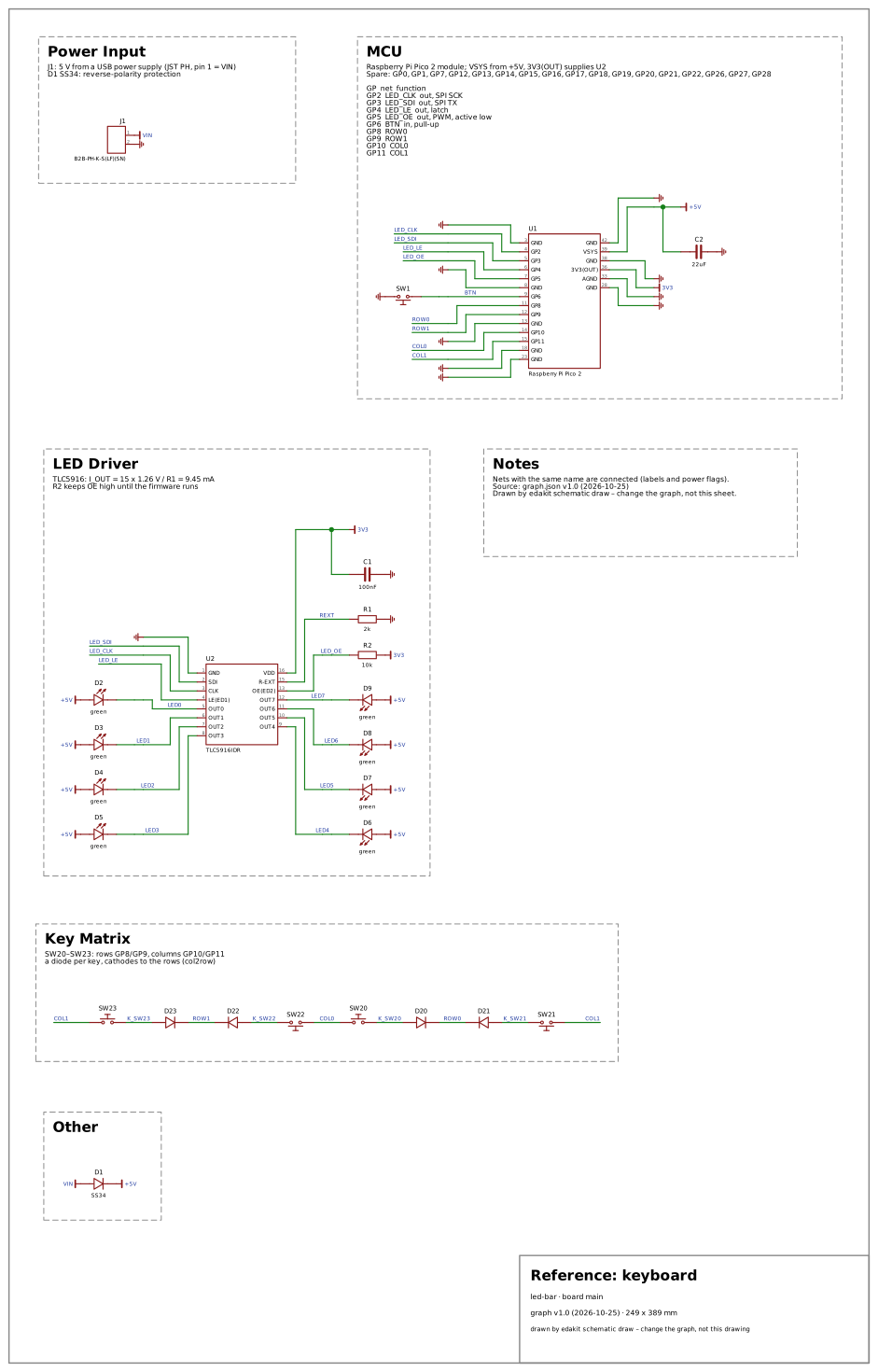
A 2 × 2 key matrix: SW20–SW23 from the rows (GP8, GP9) to an SS14 each, cathodes to the rows, anodes … the columns (GP10, GP11).
Why: A key matrix with a diode per key is the circuit of a keyboard. Its rules hold on every board, so it stands for no domain but core; it holds the diode per key and its direction.
Domains on: core · SVG
Reference: keyboard
led-bar · board main
graph v1.0 (2026-10-25) · 249 x 389 mm
drawn by edakit schematic draw – change the graph, not this drawing
Power Input
J1: 5 V from a USB power supply (JST PH, pin 1 = VIN)
D1 SS34: reverse-polarity protection
MCU
Raspberry Pi Pico 2 module; VSYS from +5V, 3V3(OUT) supplies U2
Spare: GP0, GP1, GP7, GP12, GP13, GP14, GP15, GP16, GP17, GP18, GP19, GP20, GP21, GP22, GP26, GP27, GP28
GP net function
GP2 LED_CLK out, SPI SCK
GP3 LED_SDI out, SPI TX
GP4 LED_LE out, latch
GP5 LED_OE out, PWM, active low
GP6 BTN in, pull-up
GP8 ROW0
GP9 ROW1
GP10 COL0
GP11 COL1
LED Driver
TLC5916: I_OUT = 15 x 1.26 V / R1 = 9.45 mA
R2 keeps OE high until the firmware runs
Notes
Nets with the same name are connected (labels and power flags).
Source: graph.json v1.0 (2026-10-25)
Drawn by edakit schematic draw – change the graph, not this sheet.
Key Matrix
SW20–SW23: rows GP8/GP9, columns GP10/GP11
a diode per key, cathodes to the rows (col2row)
Other
LED_CLK
LED_CLK
LED_SDI
LED_SDI
LED_LE
LED_LE
LED_OE
LED_OE
BTN
ROW0
ROW0
ROW1
ROW1
COL0
COL0
COL1
COL1
COL1
LED0
LED1
LED2
LED3
LED4
LED5
LED6
LED7
REXT
K_SW22
K_SW23
K_SW20
K_SW21
VIN
3V3
+5V
+5V
+5V
+5V
+5V
+5V
+5V
+5V
+5V
3V3
3V3
+5V
VIN
1
2
J1
B2B-PH-K-S(LF)(SN)
GND
3
GP2
4
GP3
5
GP4
6
GP5
7
GND
8
GP6
9
GP8
11
GP9
12
GND
13
GP10
14
GP11
15
GND
18
GND
23
GND
42
VSYS
39
GND
38
3V3(OUT)
36
AGND
33
GND
28
U1
Raspberry Pi Pico 2
SW1
C2
22uF
GND
1
SDI
2
CLK
3
LE(ED1)
4
OUT0
5
OUT1
6
OUT2
7
OUT3
8
VDD
16
R-EXT
15
OE(ED2)
13
OUT7
12
OUT6
11
OUT5
10
OUT4
9
U2
TLC5916IDR
D2
green
D3
green
D4
green
D5
green
D6
green
D7
green
D8
green
D9
green
R2
10k
R1
2k
C1
100nF
SW20
SW22
D22
D23
SW23
D20
D21
SW21
D1
SS34