Hardware
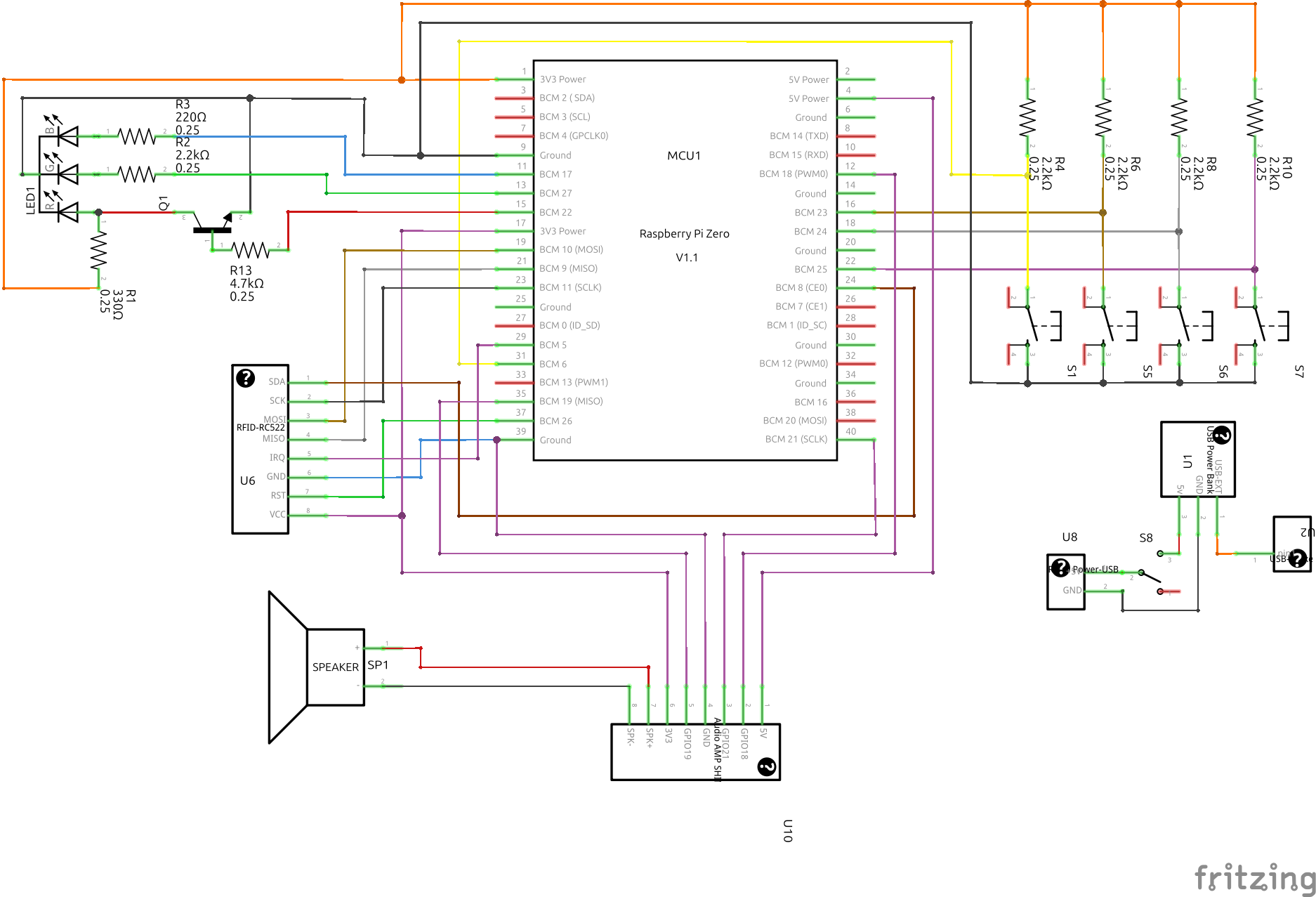
The circuit of the box and its printed parts. The key data of the components and the links to their data sheets
are in docs/hardware/.
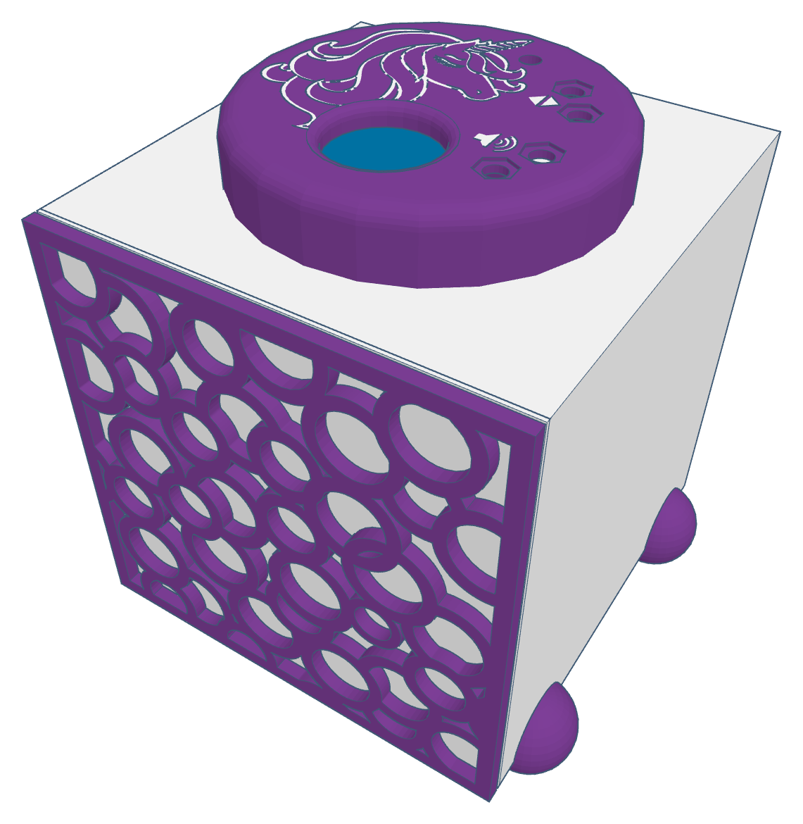
The box put together from its printed parts, as a slightly simplified 3D model.
| Folder | Content |
|---|---|
circuits/ |
the circuit of the box, drawn with Fritzing: tinyjukebox.fzz, its picture tinyjukebox_circuit.png and the parts list tinyjukebox_bom.html |
3d-parts/ |
STL files of the printed parts (December 2019), each with a picture of the same name: two views, the size in mm |
1. Circuit
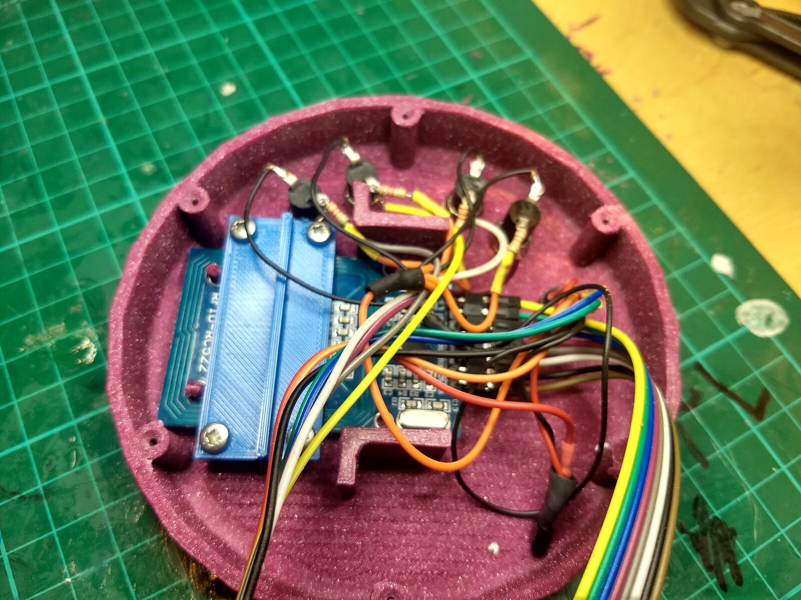
The circuit built, inside the lid of the first box (2019): the RC522 in its holder, the buttons, the LED and their resistors, the ribbon cable to the Pi.
| Part | In the drawing | Connected to |
|---|---|---|
| RFID reader RC522 | U6 | SPI0 with CE0 (GPIO 8, 9, 10, 11), RST on GPIO 26, IRQ on GPIO 5, 3.3 V |
| Audio Amp SHIM with speaker | U10, SP1 | GPIO 18, 19, 21 (I2S), 5 V and 3.3 V |
| Buttons | S1, S5, S6, S7 | GPIO 6, 23, 24, 25 against GND, each with a pull-up resistor of 2.2 kΩ to 3.3 V (R4, R6, R8, R10) |
| RGB LED, common cathode | LED1 | green on GPIO 27 through 2.2 kΩ (R2), blue on GPIO 17 through 220 Ω (R3), red on 3.3 V through 330 Ω (R1) and switched by the transistor Q1, whose base is on GPIO 22 through 4.7 kΩ (R13) |
| Power | U1, S8, U8, U2 | the power bank (U1) feeds the Pi (U8) through the switch S8; U2 is a USB socket on the power bank |
What to know about the drawing:
- The computer is drawn as a Raspberry Pi Zero. The box has a Raspberry Pi 3 Model B; its header has the same pins.
- The transistor Q1 takes the current away from the red LED while GPIO 22 is high: red is on while the pin is low. Green and blue are on while their pin is high.
- The buttons have a pull-up resistor each. The software switches on the internal pull-up of the Pi as well and debounces the buttons itself.
- The IRQ pin of the RC522 is connected to GPIO 5. The box does not use it.
- The switch S8 cuts the power between power bank and Pi: that is how the box is switched off.
The pins are those of the table in box.md, section 1, which also says what each button does.
2. Wiring
Keep the wires from the parts in the lid (buttons, LED, RFID reader) to the Pi a few centimetres away from the magnet ring of the speaker. Too close to it, the box may behave in undefined ways.
3. Printed parts
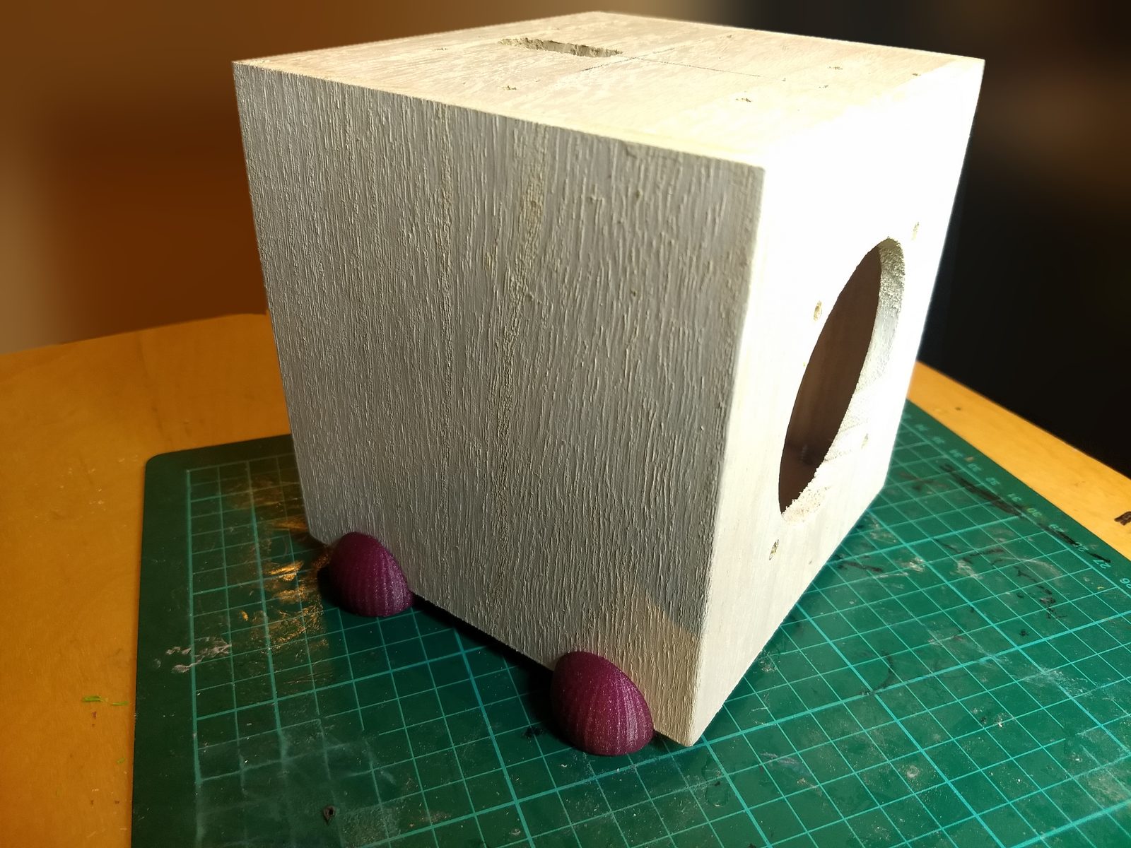
The case is made of wood; the printed parts are fixed to it.
File in 3d-parts/ |
Size in mm | Part | Photo |
|---|---|---|---|
lid.stl |
110 × 110 × 20 | round lid with a hole in the middle; on the outside the outline of a unicorn and four hexagonal recesses with their symbols, on the inside posts and two brackets | 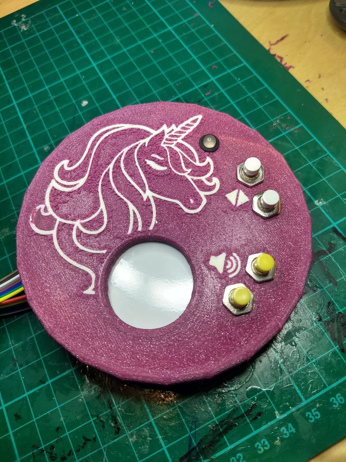 |
lid_inlay.stl |
77.8 × 78.5 × 0.7 | the unicorn and the symbols of the lid as a part of their own, for a second colour | |
front_panel.stl |
139 × 139 × 1 | square panel with a round field of holes for the speaker | |
front_grille.stl |
139 × 139 × 4 | square grille of rings, with four eyes for screws | 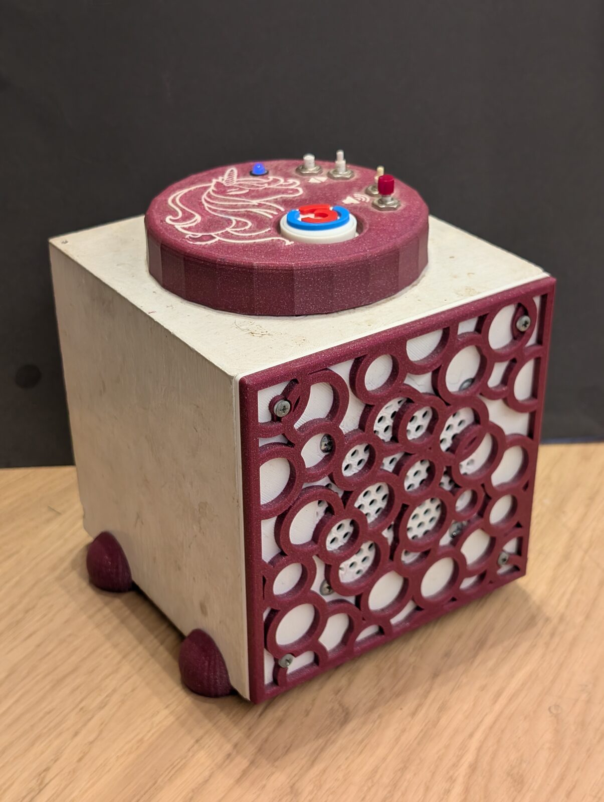 |
power_bank_mount.stl |
123 × 91.5 × 15 | frame for the power bank, with four posts and two rows of slots | 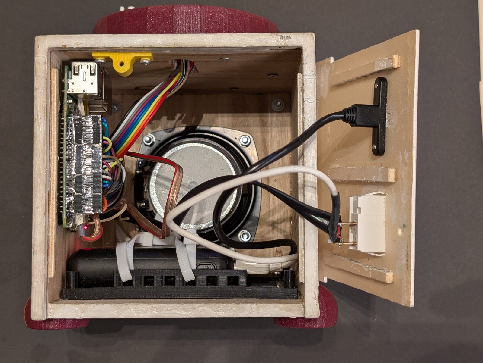 |
rfid_reader_holder.stl |
52 × 23 × 5.8 | plate with a rail and four holes, for the RFID reader | 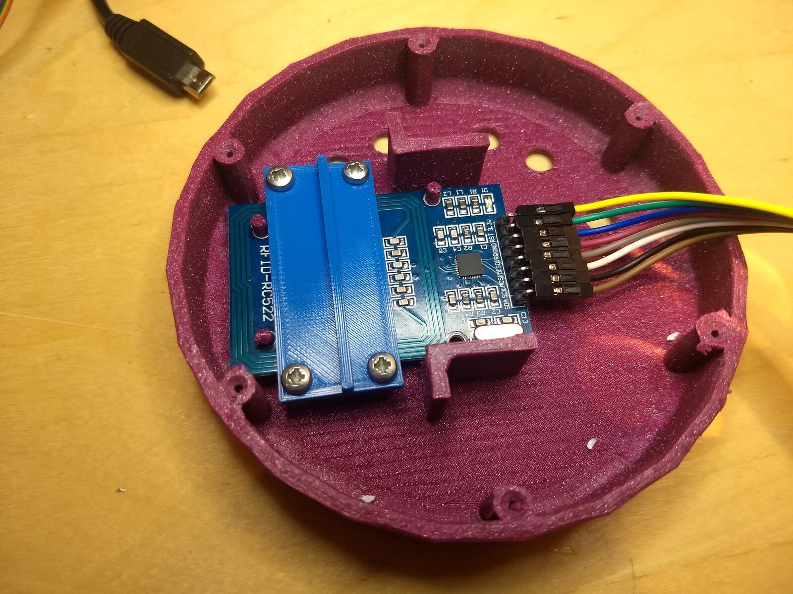 |
usb_port_bezel.stl |
44.5 × 15 × 2 | bezel with an opening for a USB port and two countersunk holes | 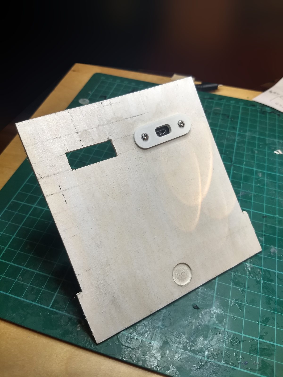 |
lock_screw_bracket.stl |
30 × 10 × 10.5 | bracket with an eye for the screw that closes the case | 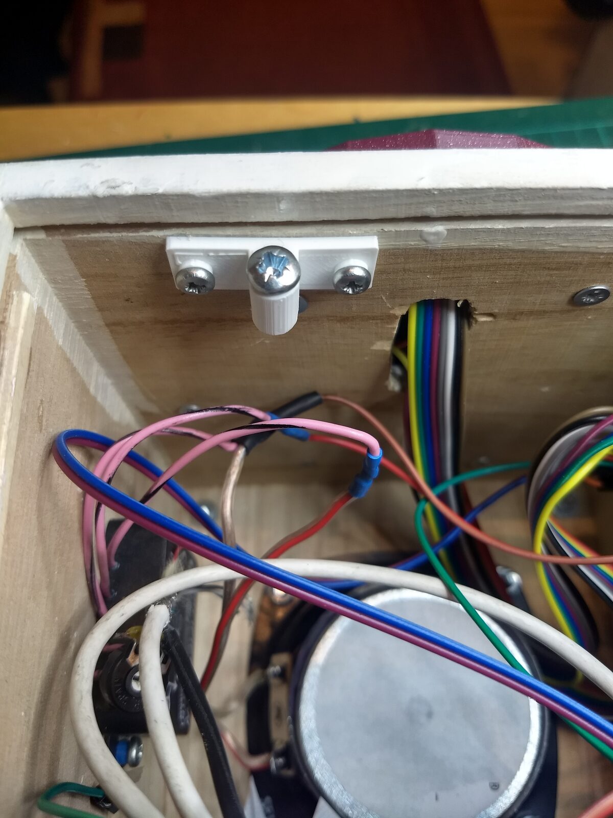 |
foot.stl |
35 × 30 × 21.7 | rounded foot with a hole for its screw | 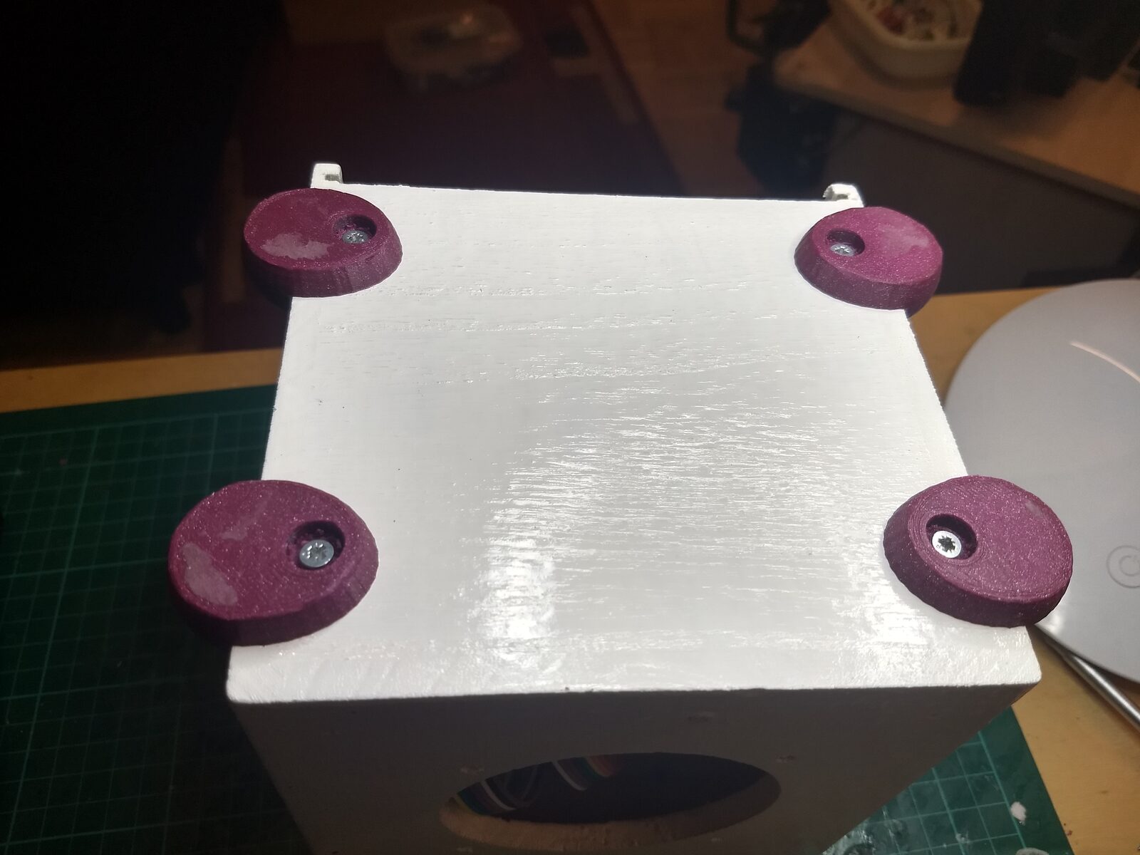 |
spacer_3mm.stl |
5 × 5 × 3 | spacer ring with a hole of 3 mm | |
figure_base_cup.stl |
28 × 28 × 8 | base of a figure, outer part: a cup, 26.2 mm wide and 7 mm deep inside | |
figure_base_plug.stl |
26 × 26 × 7 | base of a figure, inner part: the disc that fills the cup | |
figure_base_wide_plug.stl |
32 × 32 × 8 | inner part with a rim of 32 mm, for a wider base | |
figure_base_wide_cup.stl |
28 × 28 × 8 | the cup of the wider base; the same shape as figure_base_cup.stl |
4. Licence
- Printed parts (
3d-parts/): our own designs, under the MIT licence of the repository (LICENSE.txt). - Circuit (
circuits/): our own drawing, made with Fritzing. The graphics of the parts in it come from the parts library of Fritzing, which is under CC BY-SA 3.0; the drawing, its picture and the parts list are therefore under CC BY-SA 3.0 as well.