
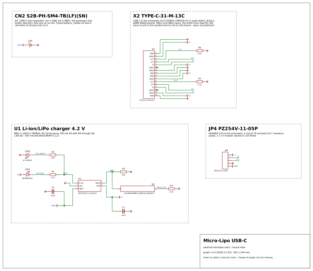
Why: the first charger among edakit's test circuits – no reference circuit has one (power is three AA cells beside USB), and no other open design charges a cell. It puts a linear Li-ion charger with its behaviour model on a published board: the current R_PROG programs, held against the MCP73831's 500 mA and the cell's 1C (LIM.i/charge, LIM.backfeed into the cell), the charger's heat at a low cell (LIM.t), a second charge current set by a solder jumper, a LiPo pack whose JST plug can come reversed (PATH.reverse on a battery holder), two status LEDs on a tri-state output – the domain power with a real charger, and HINT.lithium and HINT.charge_termination on a part makers use. Makers build and copy it everywhere: the MCP73831 with a PROG resistor, two LEDs and a JST PH socket is the charger of most hobby LiPo projects – Adafruit's Micro-Lipo boards, the same circuit on Feathers and countless clones –, so a false alarm here would meet many.
| Stage | Code | Where | Judged | Why |
|---|---|---|---|---|
| check | DOCS.file | edakit.toml | criterion | The transcription has no requirements file: what the published design must do stands in its own documents, not in edakit's form. edakit requires the file before a release (handbook 3.6); it is no point of the design. |
| check | LIM.i/charge | U1 | real | With SJ1 closed, R3 (10 kΩ) and R4 (2.2 kΩ) in parallel are 1.80 kΩ: 1000 V / 1.80 kΩ = 555 mA, above the MCP73831's 500 mA and below its PROG window of 2 … 67 kΩ (DS20001984H p. 4) – and above 1C of the 500 mAh cell the product page names for this mode. 2.5 kΩ, as the micro-USB Micro-Lipo of the same repository has, would give 500 mA; the schematic's own table says 2.0K = 500mA. |
| check | PATH.reverse | U1.3 | real | A pack whose JST plug is wired the other way round puts −4.2 V straight on the charger's VBAT (and C2): nothing on the board blocks it. Adafruit says so itself – 'For use with Adafruit LiPoly/LiIon batteries only! Other batteries may have different voltage, chemistry, polarity or pinout' – and the plug's polarity differs between makers. |
| check | PARTS.fact/reach | C15850 | lacks | A board that is sold names the SVHCs above 0.1 % (REACH Art. 33); the transcription took no supplier REACH statement for this part. |
| check | PARTS.fact/reach | C2297 | lacks | A board that is sold names the SVHCs above 0.1 % (REACH Art. 33); the transcription took no supplier REACH statement for this part. |
| check | PARTS.fact/reach | C23179 | lacks | A board that is sold names the SVHCs above 0.1 % (REACH Art. 33); the transcription took no supplier REACH statement for this part. |
| check | PARTS.fact/reach | C23186 | lacks | A board that is sold names the SVHCs above 0.1 % (REACH Art. 33); the transcription took no supplier REACH statement for this part. |
| check | PARTS.fact/reach | C25804 | lacks | A board that is sold names the SVHCs above 0.1 % (REACH Art. 33); the transcription took no supplier REACH statement for this part. |
| check | PARTS.fact/reach | C2848620 | lacks | A board that is sold names the SVHCs above 0.1 % (REACH Art. 33); the transcription took no supplier REACH statement for this part. |
| check | PARTS.fact/reach | C295747 | lacks | A board that is sold names the SVHCs above 0.1 % (REACH Art. 33); the transcription took no supplier REACH statement for this part. |
| check | PARTS.fact/reach | C4190 | lacks | A board that is sold names the SVHCs above 0.1 % (REACH Art. 33); the transcription took no supplier REACH statement for this part. |
| check | PARTS.fact/reach | C424093 | lacks | A board that is sold names the SVHCs above 0.1 % (REACH Art. 33); the transcription took no supplier REACH statement for this part. |
| check | PARTS.fact/reach | C492404 | lacks | A board that is sold names the SVHCs above 0.1 % (REACH Art. 33); the transcription took no supplier REACH statement for this part. |
| check | PARTS.fact/reach | C84256 | lacks | A board that is sold names the SVHCs above 0.1 % (REACH Art. 33); the transcription took no supplier REACH statement for this part. |
| sim | LIM.i | U1 | real | The 500 mA mode charges with 555 mA in the model, above the MCP73831's 500 mA (LIM.i/charge, a warning) – the static finding seen in the operating point. |
| sim | LIM.backfeed | CN2 | real | 555 mA into Adafruit's 500 mAh cell: above its quick-charge maximum of 1C (PKCELL 503035 specification, 500 mA), the cell the product page names as the smallest for this mode. |
| sim | LIM.i | X2 | real | In the 500 mA mode the board draws 556–558 mA; with 5.1 kΩ Rd it asks a USB-C source for Default USB Power, 500 mA from a USB 2.0 port. Default power from a USB 3.x port (900 mA) carries it. |
| sim | LIM.t | U1 | real | In the 500 mA mode the SOT-23-5 dissipates 0.57 W from a cell at 3.7 V and 1.1 W from one at 3.0 V: 157–278 °C at 230 K/W. The MCP73831 then regulates its temperature and cuts the current (DS20001984H 6.1.1.3: 1.54 W worst case) – the 500 mA the jumper promises are not reached from a low cell; edakit's model has no thermal regulation and shows the dissipation. |
- STAT not driven by the charger model: it floated, and the two LEDs carried the chain 5V – LED1 – R1 – R2 – LED2 – GND, the red one too dim while charging and the green one lit (SIM.state on LED1, LED2). The model now holds STAT low while it charges and high once the current falls below i_term_ratio of the set current: 4.3–7.5 mA through LED1 while charging, 4.2 mA through LED2 with the cell full (TD-133).
- SJ1, two pads of the board's copper bridged with solder, asked for a supplier, a REACH statement and an EasyEDA device (PARTS.supplier, PARTS.fact/reach, PARTS.verified/device): the parts entry says own.what "copper" now – nothing bought, nothing to state (TD-127).
- A charger's status LEDs, each behind its series resistor on the tri-state STAT, taken for a floating net (LVL.undefined/open_drain on STAT) – an LED cathode straight on an output counted as its load, one behind a resistor did not.
- R4 behind the solder jumper SJ1 – the 500 mA mode – counted by neither LIM.i/charge nor the simulation's charger model, which read only resistors straight from PROG to ground: the check now holds the position that programs the most, the model the contacts a load closes.
- A reversed cell carried by JP4 from its VBAT pad to 5V, and by the USB-C receptacle on to CC1 and CC2 – catalog/paths.toml let a connector pass a reversed source from every pin to every pin (PATH.reverse on U1.4, LED1.2, R5.2, R6.2): a connector now takes it on the contact it sits on and hands nothing on (TD-124).