
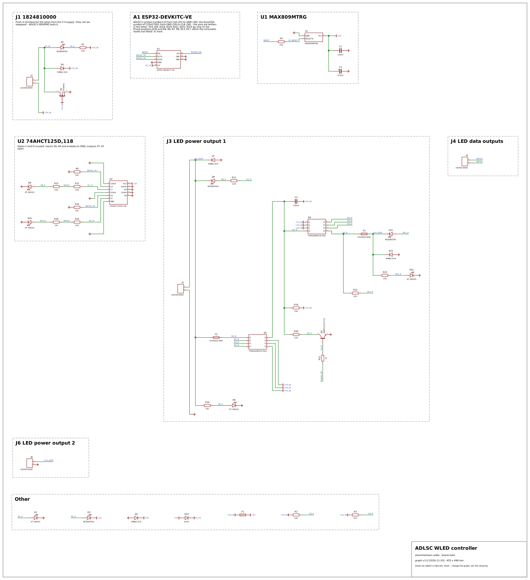
Why: the WLED controller – the board makers build to drive addressable LED strips from an ESP32 at several amperes: a 5 V supply of 10 A, the ESP32's 3.3 V data shifted to 5 V by a 74AHCT125 with 100 Ω in series, the strips' power switched by the firmware and fused per output. No reference circuit has an LED-strip output, and of the open designs the Corne feeds its SK6812s one diode below 5 V to make 3.3 V data reach them and the SparkFun converter shifts levels with BSS138s; ADLSC brings the TTL-input buffer, a reverse-polarity N-MOSFET in the ground return, a voltage supervisor on the ESP32's EN, P-MOSFET high-side switches driven from a GPIO through an NPN, glass fuses with blown-fuse LEDs, a polyfuse, TVS diodes on every 5 V rail, and an ESP32 development board plugged in behind a Schottky diode – real parts with their datasheets, in a class of board that WLED's users copy, where a false alarm would meet many.
| Stage | Code | Where | Judged | Why |
|---|---|---|---|---|
| check | DOCS.file | edakit.toml | criterion | The transcription has no requirements file: what the published design must do stands in its own documents, not in edakit's form. edakit requires the file before a release (handbook 3.6); it is no point of the design. |
| check | LIM.v | A1.2 | real | The MAX809's RESET is push-pull to its own supply, +5V (VOH ≥ 0.8 VCC), and drives the DevKitC's EN through R5 (100 Ω) – a 3.3 V pin of the ESP32 (VIH up to VDD + 0.3 V). Above 3.6 V the pin's protection carries the difference into the 3.3 V rail; an open-drain supervisor or a divider would keep EN at 3.3 V. |
| check | LIM.v | D13 | real | The SMBJ5.0CA on +5V_LED2: its stand-off voltage VR is 5.0 V, the IRM-60-5 delivers up to 5.125 V (5 V ± 2.5 %) – above VR it may leak more than its datasheet's 1.6 mA; it breaks down at 6.4 V at the earliest, so it does not clamp. |
| check | LIM.v | D4 | real | The SMBJ5.0CA across the input, +5V_IN to 0V_IN: its stand-off voltage VR is 5.0 V, the IRM-60-5 delivers up to 5.125 V (5 V ± 2.5 %) – above VR it may leak more than its datasheet's 1.6 mA; it breaks down at 6.4 V at the earliest, so it does not clamp. edakit's extremes add 0V_IN's −0.2 V (Q1's drop in the ground return). |
| check | LIM.v | D5 | real | The SMBJ5.0CA on +5V: its stand-off voltage VR is 5.0 V, the IRM-60-5 delivers up to 5.125 V (5 V ± 2.5 %) – above VR it may leak more than its datasheet's 1.6 mA; it breaks down at 6.4 V at the earliest, so it does not clamp. |
| check | LIM.v | D7 | real | The SMBJ5.0CA on +5V_LED1: its stand-off voltage VR is 5.0 V, the IRM-60-5 delivers up to 5.125 V (5 V ± 2.5 %) – above VR it may leak more than its datasheet's 1.6 mA; it breaks down at 6.4 V at the earliest, so it does not clamp. |
| check | LVL.undefined | Q3 | real | Q3's base hangs on R21 from GPIO4 alone: while the ESP32 is held in reset (by the MAX809 or the EN button), before WLED configures the pin, or with the DevKitC taken out of its sockets (the README flashes it unplugged), nothing defines it – the LED power then rests on leakage. A 10–100 kΩ from base to emitter would hold it off; the README's test (EN held: the outputs dark) shows it stays off in practice. |
| sim | LIM.i | F2 | criterion | WLED's 5 A over the two outputs puts 2.5 A through each 3 A glass fuse, 83 % of its rating, and the load fuses_3a the full 3 A – beyond edakit's 80 %. The 239 series carries 100 % for 4 hours minimum and is sized so on purpose (README: (10 A − 1 A) / 3); that the rating is the design's own limit is the README's choice. |
| sim | LIM.i | F3 | criterion | As F2: 2.5 A at WLED's limit and 3 A in fuses_3a through the 3 A fuse of the second output, beyond edakit's 80 % of its rating, which the 239 series carries for 4 hours minimum at 100 %. |
| sim | LIM.i | Q1 | criterion | With both outputs at their fuses' 3 A, Q1 in the ground return carries 6.4 A – inside the AOD442's 7 A (IDSM at 25 °C), beyond edakit's 80 % of it; 0.98 W put its junction at 84 °C (LIM.t passes). At WLED's 5 A it passes. |
| sim | LIM.range | A1 | real | The DevKitC's 5V pin gets 3.9–4.2 V: the polyfuse F1 at its 1 Ω after a trip (R1max), the SS34 and – with the LEDs lit – the supply wires and Q1 in the ground return. With the AMS1117's 1.3 V maximum dropout the WROVER-E would see less than its 3.0 V; vin_min_v 4.3 V is derived from both (entry C20437001). With F1 at its 0.15 Ω and a typical dropout it works – a worst case, not the typical board. |
| sim | LIM.range | U2 | real | +5V sags to 4.23–4.49 V with the LEDs lit: the supply wires and Q1 lift GND by 0.2–0.3 V, F1 at its R1max drops 0.36 V – the 74AHCT125 leaves its 4.5 V minimum. The same +5V reaches the MAX809's own threshold (4.27–4.49 V): in the worst case the supervisor resets the ESP32 as the LEDs come on. The polyfuse in front of the 5 V logic is the cause. |
| sim | LIM.v | D1 | real | The reverse-polarity LED D1 sits across the input the other way round in normal operation: 5.0–5.1 V reverse at the IRM-60-5's upper tolerance, against the LED's 5 V VR (NCD0805R1, which stands in for the schematic's 'Red'). |
| sim | SIM.state | D12 | criterion | D12 – LED output 2's indicator, 10 kΩ from +5V_LED2 – gets 0.2 mA, below edakit's 1 mA for an LED that is on. The 10 kΩ dim it on purpose: the README tests it as lit ('D2 green is on', 'D6 and D12 will get brighter'). |
| sim | SIM.state | D2 | criterion | D2 – the power LED, 10 kΩ from +5V_IN – gets 0.2 mA, below edakit's 1 mA for an LED that is on. The 10 kΩ dim it on purpose: the README tests it as lit ('D2 green is on', 'D6 and D12 will get brighter'). |
| sim | SIM.state | D6 | criterion | D6 – LED output 1's indicator, 10 kΩ from +5V_LED1 – gets 0.2 mA, below edakit's 1 mA for an LED that is on. The 10 kΩ dim it on purpose: the README tests it as lit ('D2 green is on', 'D6 and D12 will get brighter'). |
- The bidirectional SMBJ5.0CA across the terminal (D4) judged as one direction – reached by the reversed 5 V on both pins (PATH.reverse on D4.1, D4.2): the parts schema has values tvs "bidirectional" now, which PATH.reverse tolerates and LIM.v holds either way (TD-132).
- The reverse-polarity N-MOSFET in the ground return (Q1) unknown to PATH.reverse, which walked from J1's pins as if GND were the return – 18 findings on the plus side and on Q1 itself (D1.2, D3.1, D5.1, Q1, Q2, Q4, R1.1, R2.1, R3.1, R19.1, U1.3, U2.14, C2.1): a low-side N-MOSFET is now a cut of catalog/paths.toml [reverse], and only the parts between the terminal's own nets count (TD-125).
- The gate of the reverse-polarity N-MOSFET in the ground return, tied straight to the net the supply comes in on (Q1 on +5V_IN), taken as floating (LVL.undefined on Q1).