
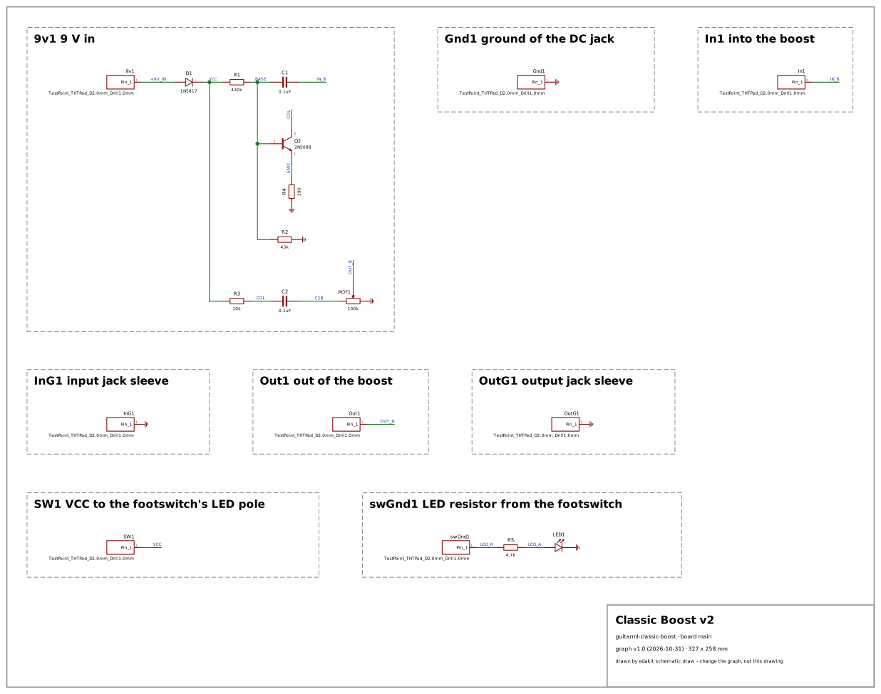
Why: a one-transistor boost, the stage many builders start with. Beside it the combo's transistors are followers – their bias hardly depends on the gain. The boost is the one stage whose operating point the transistor's spread moves: a common-emitter stage, its base held by a divider, its gain set by the collector and emitter resistors – the case of FT-17's corners and of a gain an AC run can show. It also has no IC at all: nothing types its supply and ground, which showed a false alarm, fixed since (findings.toml, [[fixed]]).
| Stage | Code | Where | Judged | Why |
|---|---|---|---|---|
| check | DOCS.file | edakit.toml | criterion | The transcription has no requirements file: what the published design must do stands in its own documents, not in edakit's form. edakit requires the file before a release (handbook 3.6); it is no point of the design. |
| check | PARTS.verified/device | POT1 | lacks | POT1, the volume (100K, the parts list's A100K): the TT Electronics P160 order code that stands in has no LCSC number in the catalogue, and a KiCad design names no EasyEDA device. |
| check | STRUCT.prefix | SW1 | criterion | SW1 is the schematic's own reference of a wire pad – VCC to the footswitch's LED pole (board label 'SW'); KiCad does not tie references to kinds, edakit reads SW as a switch. |
- The pads 9v1, Gnd1, In1, InG1, Out1, OutG1, SW1 and swGnd1 – the board's plated pads for a wire or a probe asked for an LCSC part or an EasyEDA device (PARTS.verified/device on the eight): their entry says own.what "copper" now – the board's own, nothing to buy or pick (TD-127).
- The 2N5088's base, held by 430 kΩ from VCC and 43 kΩ to ground with 390 Ω under the emitter, judged as floating while 'the firmware is not running' (LVL.undefined): the board has no IC, so no pin typed VCC or ground as a rail, and a resistor to ground did not count.