4 The parts database
For whoever writes, checks or looks up a parts entry – by hand, or with the skills part-search and own-part and the agent part-selector. After this chapter you can find a part, write and sign off its entry, keep its datasheet with the project, and enter a part nobody sells. The short way: Settle parts and cost.
In short. Every part has one JSON entry in hardware/parts/: pin types and roles, limits, parameters, SPICE models,
leads, and who checked it against which datasheet (the fields, 4.1). The agent part-selector compares candidates at the
project's distributors and writes the entry it recommends; the parts library has signed entries to copy (finding parts,
4.2). An entry is signed off against its datasheet, kept with the project, and a critical part gets the second check M-1
(signing off, 4.3; the datasheets, 4.6). A changed entry changes the circuit hash. A part nobody sells – a board of your
own – gets an entry derived from its project (own parts, 4.5).
Each part has one JSON file in hardware/parts/, named
- by its LCSC number:
hardware/parts/C17414.json; - for a part bought from another distributor, by its manufacturer part number, characters a file name cannot hold
replaced by
_:hardware/parts/RC0805FR-0710KL.json; - for a part nobody sells, such as a board of your own, by the name it was given (own parts, 4.5).
A component finds its entry by lcsc, and without one by part = the entry's mpn. The entry holds what the
datasheet says, in a form the checks and the simulation can use: pin types and roles, limits, parameters, SPICE
models, lead dimensions, the part's height and its mated plug, and who checked it against which datasheet revision.
Examples: the Christmas bell's parts.
4.1 Fields
| Field | Content |
|---|---|
lcsc, mpn, manufacturer |
identification. lcsc equals the file name, mpn is what a component names in part – STRUCT.identity compares them, with the kind and the value parameters. With a maker that matches by MPN (bom.match = "mpn" in its profile: PCBWay, Eurocircuits, AISLER; [cart]), mpn and manufacturer are required for every assembled part (PARTS.fact/mpn) and go into bom_<board>_mpn.csv, for AISLER into the components of the ODB++ (kicad-cli, 16.5) |
order |
where a part bought separately is ordered, supplier → order code: {"rs": "223-0562", "farnell": "…"}. A value may be {code, moq, step} with the supplier's minimum and pack size, {"lcsc": {"moq": 20, "step": 20}} (the LCSC code defaults to lcsc). The first supplier is the default of edakit order. PARTS.supplier warns about a bom: false part with neither an LCSC number nor order – a C99… library number counts as none, LCSC does not sell it |
kind |
resistor, capacitor, crystal, inductor, fuse, diode, led, led_rgb, npn, pnp, pmos, nmos, njfet, pjfet, switch, dip_switch, button, potentiometer, battery_holder, buzzer, relay, connector, ic, module, motor, solenoid, speaker, heater, optocoupler, esd_array, led_strip, varistor |
package, footprint |
the footprint name must equal the EasyEDA footprint (SYNC.footprint compares it with the PCB) |
footprint_data |
optional: the footprint as data – origin, pads, outline and print in mm –, from which edakit part build builds the project's copy and to which SYNC.footprint holds it; an own footprint as text (4.5) |
jlc_class |
Basic / Extended Part; PARTS.stock warns when JLCPCB's catalogue lists another class |
datasheet |
url, pinout_page; edakit part fetch keeps the PDF beside the project, not in the entry (4.6) |
pins |
pin number → the keys of the pin table below |
address |
a device on a bus: {"base": 104, "pins": {"9": 1}, "also": [112], "on": "6"} – its address with every address pin low, what each pin adds when high (by pin number) – or, for a pin with four states, what it adds tied to each: {"7": {"low": 0, "high": 1, "sda": 2, "scl": 3}} (INA219, INA226: A0 on GND, VS, SDA or SCL) –, further addresses it always answers to (a PCA9685's All-Call), the pin whose net is the bus (default: the pin with the role sda). Two devices on one bus at one address are REQ.forbidden/address (a warning); a pin the graph does not hold high or low leaves the device out |
configs, config_default |
the configurations a part runs in, by name – {"5v": {…}, "3v3": {…}}. Each has about and what differs from the entry: limits and values (a key replaces the entry's, null removes it), pins (per pin number the keys that differ – type, role, thresholds, strap, needs; null removes one), needs and address (replace the entry's, null removes them). A component names its config ("config": "3v3", 3.1); without one config_default applies, without that the entry as it stands. edakit part lint holds every config to the schema as the entry it makes (configs.<name>: …) and every when to the configs; a component's config the entry does not know is STRUCT.entry. In the library: CH340C and CH340G at 5 V or 3.3 V (V3 a 100 nF capacitor at 5 V, on VCC at 3.3 V), the CP2102 with its regulator in use or bypassed, the SSD1306 panel C2890596 in I2C (D0 SCL, D1 and D2 SDA, the BS straps) or 4-wire SPI, the DS18B20 powered or in parasite power, the DS3231 with a backup cell, on VBAT alone or without a battery, the HX711 with or without its regulator, the BME280 in I²C (its default: CSB tied to VDDIO, SDO not floating, the address and the roles sda/scl), 4-wire SPI (SDO a tri-state output) or 3-wire SPI (SDO not connected) |
matrix |
a microcontroller or module whose GPIO matrix routes peripherals to any GPIO: the fn kinds it routes, from its datasheet's GPIO matrix section – ["uart", "i2c", "i2s", "pwm", "can"] on the ESP32. A net's fn of those kinds is then served by any GPIO that can drive it (an input line, rx, also by an input-only pin), the nets of one fn_bus need no common instance, and PWM has no fixed slice (REQ.function). Without it only the pins' functions count, and only those of microcontrollers and modules: a peripheral's own functions do not answer for the MCU |
antenna |
a module with a printed antenna: {"keepout_mm": [x0, y0, x1, y1], "edge_mm": 1} – the area around the antenna that stays free of copper, in mm in the footprint's frame (rotation 0, top), taken from the module's datasheet, and how far inside the board's outer edge that area may lie at most, from the maker's layout guide (Espressif: 1 mm for the ESP32 and ESP32-S3 modules, 0 for the ESP32-C3's). The gate holds the board's copper on both layers to the area where the part sits, and the area to the outer outline – a cut-out inside the board is no edge (GEO.keepout, grade edge, warnings while new); a radio without either is listed by edakit check --coverage |
hints |
warnings of the datasheet for the part as a whole; edakit check shows them and the pin hints of connected pins |
hot_loop |
switching regulators: the pin roles of the loop that carries the pulsed current, from the datasheet's layout section – a buck ["vin", "sw", "gnd"], an asynchronous boost ["sw", "gnd"]; a ground pin without a role is gnd. REQ.missing wants a layout.loops entry on each of their nets and on the net behind a diode on sw |
symbol |
optional: the sides of the box edakit schematic draw draws for an IC or module – {"left": [pins], "right": [pins], "top": [pins], "bottom": [pins]}; without it the pins run as on a DIP package (6.5). With footprint_data and its "symbol": "box" also the box edakit part build draws as the copy's symbol in EasyEDA (4.5) |
limits |
what the part withstands or needs, per kind below – the engine LIMITS holds every quantity to them |
values |
what the simulation and the calculations read, per kind below; behavior for ICs (chapter 5) – matrix_driver for a multiplexing LED driver (MAX7219): the LEDs between its segment and digit pins have no DC state, the simulation lists them as information instead of SIM.state or SIM.driver |
spice |
{"model": ".model SS34 D(IS=20u N=1.2 RS=0.04 …)"} for diodes and transistors |
lead |
through-hole parts only: lead cross-section per pad number or "*": shape (square, round, rect), a_mm, b_mm, tol_mm, hole_rec_mm, source – checks GEO.hole, before the layout on the footprint geometry and in the gate on the drill file; the ring a widened hole leaves: GEO.ring; a footprint with plated holes and no lead keeps GEO.hole pending; optional length_mm, the lead length below the seating plane – the mechanical model gives its protrusion (7.4) |
body |
optional: {"h_mm": 2.3}, the height of the body above the board, on the side the part sits on – for the mechanical model (7.4); box [x0, y0, x1, y1] in footprint mm (relative to the part's origin at 0° on TOP, as mate), the body seen from above where it is larger than the footprint – a coin cell standing out of its holder, from the holder's drawing and the cell's size: GEO.silk warns about print under it beyond the footprint, silk apply places designators beside it (7.7) |
mate |
optional, for a connector: its mated plug with the strain relief, {"box": [x0, y0, x1, y1], "h_mm": 6.5, "exit": "+y"} – box in footprint mm (relative to the part's origin at 0° on TOP, as pcb dump measures it), h_mm its height above the board, exit the direction the cable leaves the box: +x, -x, +y, -y, or +z (away from the board). pcb plan checks it (7.4) |
joined |
optional: pins the part joins inside, as groups – [["4", "29"]], a module's two GND pins. The plan of a perfboard counts each group as one node (PERF.net, 7.9); a button's pins that share a role are joined without it |
pad_map |
only when pad numbers are deliberately swapped on the placed part: {PCB pad: library pad} – check SYNC.footprint |
sources |
where every value comes from; "assumption …" marks what must be checked with extra care – also a value taken from a sibling part or the series. The gate protocol lists every source with the word "assumption" (8.2) |
compliance |
for the regulatory review (M-6, chapter 15): rohs (true, false or the exemption), reach (the supplier's SVHC statement, or "none above 0.1 %" with its source: a board given away or sold names it for every part, else PARTS.fact/reach – information for a gift, a warning for a sale), radio for a part that transmits – bands_mhz ([[from, to], …] in MHz: the bands it can transmit in, as datasheet or certificate state them), max_dbm (the conducted power at the RF port, as datasheets state it – not the radiated power), antenna_dbi (the gain of the antenna it transmits through in the product, from the module's datasheet or certificate), eirp_dbm (optional: the e.i.r.p. where a certificate states it), doc (URL of the EU declaration of conformity); its e.i.r.p. is eirp_dbm, else max_dbm + antenna_dbi, and LIM.eirp holds it to the limit of the band (3.3) –, or "none" for a part that does not transmit: a part of graph type module or microcontroller states one of the two, else PARTS.fact reports it (information, for a board that is sold a warning), and every part the BOM lists (bom not false) states rohs, else PARTS.fact/rohs, graded the same; source (page and date). This is support for the review, not legal advice: nothing in it is legally guaranteed, and it makes no claim to be correct (chapter 15) |
verified |
null or the sign-off: by, date, datasheet (revision), checked (list), open (list: a text, or {"text": "…", "when": "order"} – when names the phase whose manual check answers it: order the assembly preview M-2, acceptance the delivered board M-4), optional datasheet_sha256 (the file signed against, as edakit part fetch recorded it), optional second_check (the independent M-1 review). The gate protocol lists the open points (8.2) |
own |
a part nobody sells (4.5): what – pcb (a board of an edakit project), bin (from your stock, no longer to be had), handmade, copper (the board's own copper – a solder jumper, a test pad, a pad for a wire: no supplier, no compliance facts, no LCSC part or EasyEDA device asked; its pads are the layout's); for pcb its source: project, connectors, graph_version, state_sha256 (the board's circuit hash), and in the copy path, commit, repo, released – SYNC.source compares them |
Pin keys
Every pin has name, type, role and v_max_v; the other keys come from the datasheet where they apply.
| Key | Content |
|---|---|
name |
as in the EasyEDA symbol and identical to the graph – SYNC.schematic compares them |
type, role |
the pin type and the role, below; for polarised parts the role follows the footprint's polarity print when symbol and footprint disagree |
strap |
"high"/"low": level the pin needs at reset (LVL.boot) |
pull, pull_ohm |
"up"/"down": internal or built-in pull resistor, with pull_ohm if known (REQ.missing, LVL.boot) |
hint |
a warning from the datasheet, e.g. "ADC2: no analog reads while WiFi is on" |
print |
on a module's pin: its name as the board prints it, from the pinout page – "D2" where the symbol says PD2. edakit schematic draw writes it beside the symbol's name in brackets, where the two differ, and nothing else reads it |
adc |
on a pin that converts: {"range_v": [0.15, 2.45], "r_source_max_ohm": 10000, "c_hold_min_f": 1e-7} – the window the converter reads in the attenuation the firmware uses, the source resistance it allows, the hold capacitor that lifts that limit. LIM.range/adc holds a net with fn: adc to the window in every scenario, REQ.value/adc the resistors on it, both warnings |
z_in_ohm |
an input's impedance, for the load on an instrument input |
short_proof |
true where a pin may go to a cable without a series resistor – REQ.missing/leave leaves it alone |
clamp |
"none" on an output without clamp diodes of its own – the L298's bridges –, "internal" where it has them: REQ.missing/clamp asks for a diode to the supply and one from ground where such an output drives a winding or a connector |
windows |
on a configuration pin that reads its setting by voltage: [{"state": "right", "min_v": 0.825, "max_v": 1.245}, …], the windows the datasheet guarantees – between one trip point's maximum and the next one's minimum –, with the pin's pull and pull_ohm in the operating point: REQ.value/window |
drive |
"open_drain" or "tristate" on an output that lets go of its line: such outputs share a line without LVL.contention, and a line only they drive needs a pull-up (LVL.undefined/open_drain). "bridge" on a motor driver's half-bridge output, driven high or low while enabled: it defines its net like a push-pull output |
state |
"high", "low" or "off" on an output or bidirectional pin: where behaviour logic holds it in the simulation – the CH340's TXD high when idle; off on an output without a logic level, the MPU-6050's REGOUT. A component's states overrides it (the graph's format, 3.1; the netlist, 5.1) |
biased |
true on an analog input the part holds at its own DC level – an amplifier input at half its supply inside, the PAM8403's INL/INR: a net only a coupling capacitor reaches has its level, no LVL.undefined/analog |
float_ok |
true where the datasheet allows an unused input to float – otherwise an IC input in nc is LVL.undefined/nc. false on a bidirectional pin the part reads and that must not float – the BME280's SDO choosing its address –, which LEVELS then holds like an input |
needs |
what the pin needs from the circuit, from the datasheet's application section – the pin needs below |
functions |
on MCU and module pins: what the pin-mux table offers, <peripheral><instance>.<line> – ["spi0.sck", "uart0.cts", "i2c1.sda", "pwm1.a", "uart0.tx"], adc0; for PWM the instance is the slice and the line the channel. [] = no free function (used on the module), no key = unknown (REQ.function) |
v_op_min_v, v_op_max_v |
from the recommended operating conditions: a supply pin's range where it differs from the part's vdd_op_min_v/vdd_op_max_v |
vih_v or vih_ratio, vil_v or vil_ratio |
from the recommended operating conditions: the thresholds of one input pin, where they differ from the part's (LVL.threshold) |
out_edge, t_pd_ns |
on a serial output (SDO, Q7) of a clocked part: "rising"/"falling", the clock edge after which it changes, and [min, max], the clock-to-output delay at the part's supply, null where the datasheet gives none – edakit check shows them with HINT.readback |
Pin needs (needs) are a list of {"what": "capacitor", "c_min_f": 1e-6, "c_max_f": 10e-6, "source": "…"}.
what is one of capacitor (to ground), pull_up (to a supply), pull_down (to ground), series_resistor,
to_ground, never_to_ground; the three resistors each take r_min_ohm/r_max_ohm, a capacitor c_min_f/c_max_f,
either bound optional. Examples: an ESP32's EN with 10 kΩ and 1 µF, a regulator's output capacitor, USB series
resistors, MAX6675 T− on ground and MAX31855 T− never. REQ.missing, REQ.value and REQ.forbidden hold them, grade
pin, a warning.
A capacitor's c_min_f counts the capacitance left after DC bias (grade bias, the capacitors' dc_bias below). A
regulator whose output capacitor's ESR must lie in a window gives esr_min_ohm/esr_max_ohm (TI's LM1117: 0.3 …
22 Ω), held to the capacitors' esr_ohm (grade esr). A need with when holds only in that config – a name of the
entry's configs, a list of names – or, with "connected", only while the pin is in a net: an INA226's ALERT wants
its pull-up where it is used, a DS18B20's VDD goes to ground in parasite power, a DS3231's VBAT wants a capacitor as
the primary supply.
Pin types (type): passive, input, output, bidirectional, power_in, power_output, ground, analog,
current_sink, no_connect, mechanical. LVL.undefined, LVL.contention, REQ.missing and PATH.unfed work with them:
power_in needs a capacitor and a net that a supply reaches, a ground pin the ground net, two outputs on one net
are a conflict, an input needs a driver. An MCU pin that can only read (the ESP32's GPIO34–39) is input, even with
the role gpio: the simulation refuses to drive it (LVL.direction).
Pin functions (functions) come from the MCU's pin-mux table, not from memory: the example's Pico 2 entry
(tests/fixtures/led-bar/hardware/parts/C41407547.json) has them for the RP2350, from the pico-sdk headers it names
in sources – any RP2350 module takes the same list per GPIO. On the RP2040 and RP2350 the PWM slice of GPIO n is
(n >> 1) & 7 and the channel a for even, b for odd n.
Pin roles
Pin roles (role) tell the code what a pin does, independent of its name:
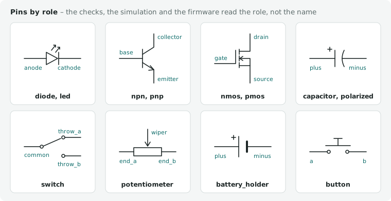
| kind | roles |
|---|---|
| capacitor | the pin numbers 1, 2; a polarized one plus, minus |
| crystal | the pin numbers 1, 2 – a crystal of four pads: the quartz on 1 and 2, the lid pads ground |
| diode, led | anode, cathode |
| led_rgb | common cathode: anode_red, anode_green, anode_blue, cathode; common anode: anode, cathode_red, cathode_green, cathode_blue – a pin with the role anode makes it a common anode |
| npn, pnp | collector, base, emitter |
| pmos, nmos | drain, gate, source; the second channel of a dual part drain_2, gate_2, source_2 |
| njfet, pjfet | drain, gate, source |
| switch | common, throw_a, throw_b; a switch of several poles (a 3PDT footswitch) common_2, throw_a_2, throw_b_2, common_3 … – every pole follows the one actuator in the simulation |
| button | a, b (pins connected inside share a role) |
| dip_switch | a1…aN, b1…bN – N is values.positions (default 8): the simulation closes switch 1 … N |
| potentiometer | end_a, wiper, end_b |
| battery_holder | plus, minus (several cells: plus_a, minus_a, …) |
| buzzer | plus, minus |
| relay | coil_plus, coil_minus, common, no, nc; a second contact set (DPDT) common_2, no_2, nc_2, and so on – each set switched by the simulation |
| motor, solenoid, speaker | plus, minus (a motor's and a solenoid's winding coil_ohm, a speaker's impedance_ohm: the simulation's resistor; a switched winding needs its flyback diode, REQ.missing) |
| heater | the pin numbers (value_ohm: its resistance, LIM.p its power) |
| optocoupler | anode, cathode, collector, emitter (vf_v, vf_at_a of the LED; ctr_min_ratio: the transistor passes at least that share of the LED current); a PhotoMOS output load_a, load_b with behavior: "photomos", r_on_ohm, if_on_a (the LED current that guarantees on – the datasheet's maximum operate current), if_off_a (guaranteed off – its minimum turn-off current), i_leak_a, and limits v_load_max_v, i_load_max_a (5.1) |
| esd_array | io1 … io8 (each protected line; two pins of one line share the role), vbus (the steering rail), gnd – limits.vrwm_max_v (the rail's stand-off: LIM.v holds the rail to it without margin), values vbr_min_v, vf_v, vf_at_a, c_io_f; HINT.esd counts the lines on its io pins as guarded |
| led_strip | vdd, gnd, din at the start, vdd_end, gnd_end, dout at the far end (cin, cout: a clocked strip's clock) – the pin numbers are the entry's own; the strip's length is the component's (3.1) |
| varistor | the pin numbers 1, 2 (v_rms_max_v, v_max_v: its VRMS and VDC, held without derating – on an AC net the first, 3.1; designator prefix RV) |
| connector | free (pin1, …); vbus/gnd for a supply input; line, neutral for a mains input (a terminal: PATH.unfed takes the module behind it as fed); cc1, cc2 on a USB-C receptacle (REQ.missing:cc; a module or breakout without these roles: values.usb_c) |
| ic, module | as the behaviour model needs them: vin, vout, gnd, vsys, 3v3, gpio, rext, out, oe_n, vdd; sda, scl for I2C pins (REQ.missing); on shift registers and LED drivers sdi, sdo (serial data in and out) and the outputs numbered out0 … outN where their order matters – the simulation reads them as out, the firmware contract numbers its channels by them (3.5) |
Limits and values
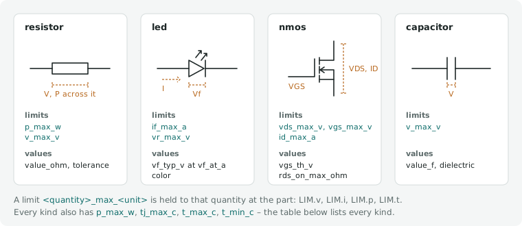
What edakit part lint holds an entry to and the engines read, per kind – generated from edakit/catalog/kinds.toml
(python -m edakit.catalog.handbook --write):
| kind | limits | values |
|---|---|---|
| every kind | p_max_w, rth_ja_k_per_w, tj_max_c, t_max_c, t_min_c |
– |
resistor |
v_max_v |
value_ohm, r_max_ohm, tolerance |
potentiometer |
v_max_v |
value_ohm, tolerance, adjust |
capacitor |
v_max_v, vr_max_v, i_ripple_a |
value_f, dielectric, polarized, tolerance, dc_bias, esr_ohm |
crystal |
– | f_hz, c_load_f |
inductor |
i_max_a, i_sat_a |
value_h, dcr_ohm |
fuse |
v_max_v, i_max_a, i_hold_a, i_trip_a |
r_min_ohm, r_max_ohm, i_hold_vs_temp |
diode |
vr_max_v, if_max_a, ifsm_max_a |
vf_v, vf_at_a, ir_a, ir_at_v |
varistor |
v_rms_max_v, v_max_v |
v_varistor_v, v_clamp_v |
led |
vr_max_v, if_max_a |
color, vf_typ_v, vf_min_v, vf_max_v, vf_at_a, rs_ohm, vf_vs_if |
led_rgb |
vr_max_v, if_max_a |
vf_typ_v, vf_min_v, vf_max_v, vf_at_a, rs_ohm, vf_vs_if |
npn |
vce_max_v, veb_max_v, ic_max_a |
hfe_min, hfe_max, vce_sat_v, icbo_a |
pnp |
vce_max_v, veb_max_v, ic_max_a |
hfe_min, hfe_max, vce_sat_v, icbo_a |
njfet |
vds_max_v, vdg_max_v, vgs_max_v, ig_max_a, id_max_a |
idss_a, vgs_off_v |
pjfet |
vds_max_v, vdg_max_v, vgs_max_v, ig_max_a, id_max_a |
idss_a, vgs_off_v |
nmos |
vds_max_v, vgs_max_v, id_max_a, is_body_max_a |
vgs_th_v, rds_on_max_ohm, vsd_v_at_1a |
pmos |
vds_max_v, vgs_max_v, id_max_a, is_body_max_a |
vgs_th_v, rds_on_max_ohm, vsd_v_at_1a |
switch |
v_max_v, i_max_a, i_contact_max_a, i_switch_max_a |
r_on_ohm, force_n, min_load_a |
dip_switch |
v_max_v, i_max_a, i_contact_max_a, i_switch_max_a |
r_on_ohm, min_load_a, positions |
button |
v_max_v, i_max_a, i_contact_max_a, i_switch_max_a |
r_on_ohm, force_n, min_load_a |
battery_holder |
i_max_a, v_max_v |
r_contact_ohm |
buzzer |
v_max_v, i_max_a |
coil_ohm |
relay |
v_coil_max_v, i_max_a, v_max_v, i_contact_max_a, i_switch_max_a |
coil_ohm, v_operate_v, v_release_v, r_contact_ohm, min_load_a |
connector |
v_max_v, i_max_a, i_contact_max_a, v_rms_max_v |
pitch_mm, r_contact_ohm, r_source_ohm, usb_c |
ic |
vdd_max_v, vdd_op_min_v, vdd_op_max_v, vin_min_v, vin_max_v, vout_max_v, i_out_max_a, vin_rel_max_v, i_supply_pin_max_a, f_max_hz, r_sense_min_ohm, f_sck_max_hz, f_scl_max_hz, gpio_i_max_a, gpio_i_total_max_a |
behavior, vout_v, dropout_v, iq_a, efficiency, idd_max_a, iout_gain, iout_accuracy, vout_knee_v, vrext_v, vih_v, vil_v, vih_ratio, vil_ratio, first_bit_to, vout_swing_v, vicm_v, r_out_ohm, comparator, gain_min_ratio, f_clock_hz, vref_v, i_load_min_a, prog_v, icc_a, i_a, i_core_a, i_core_min_a, gpio_r_out_ohm, regulator, vdd_shunt_v, i_shunt_max_a, pd_request_v, r_on_ohm, vgs_th_v, r_on_high_ohm, r_on_low_ohm, v_headroom_v, uvlo_v, v_pre_v, i_pre_ratio, i_term_ratio, v_ovp_v, v_ovp_release_v, v_uvp_v, v_uvp_release_v, v_ocp_v, v_scp_v, vsense_v, duty_max_ratio, ripple_ratio |
module |
vdd_op_min_v, vdd_op_max_v, vin_min_v, vin_max_v, vsys_min_v, vsys_max_v, i_out_max_a, gpio_v_max_v, gpio_i_max_a, gpio_i_total_max_a, f_max_hz, f_sck_max_hz, f_scl_max_hz |
behavior, regulator, v_io_v, vout_v, dropout_v, efficiency, i_core_a, i_core_min_a, gpio_r_out_ohm, iq_a, vih_v, vil_v, vih_ratio, vil_ratio, usb_c, f_clock_hz |
motor |
v_max_v, i_max_a |
coil_ohm |
solenoid |
v_max_v, i_max_a |
coil_ohm |
speaker |
v_max_v |
impedance_ohm |
heater |
v_max_v |
value_ohm |
optocoupler |
if_max_a, vr_max_v, vce_max_v, ic_max_a, v_load_max_v, i_load_max_a |
vf_v, vf_at_a, ctr_min_ratio, behavior, r_on_ohm, if_on_a, if_off_a, i_leak_a |
esd_array |
vrwm_max_v |
vbr_min_v, vf_v, vf_at_a, c_io_f |
led_strip |
vdd_op_min_v, vdd_op_max_v |
pixels_per_m, i_pixel_a, i_idle_a, r_vdd_ohm_per_m, r_gnd_ohm_per_m |
Per pin: v_max_v, v_op_min_v, v_op_max_v, vih_v, vil_v, vih_ratio, vil_ratio, pull_ohm, v_min_v, v_rel_max_v, v_max_powered_v, i_max_a, i_inject_max_a, r_load_min_ohm, c_load_max_f, pull_v, c_in_f, v_rms_max_v; and name, type, role, strap, pull, hint, functions, out_edge, t_pd_ns, needs, drive, float_ok, adc, z_in_ohm, short_proof, clamp, windows, biased, ref, rel_ref, state, print. Every name ends in its unit: _v V, _a A, _w W, _ohm Ω, _f F, _h H, _c °C, _hz Hz, _dbm dBm, _dbi dBi, _mm mm, _n N, _s s, _ns ns, _k_per_w K/W, _ratio 1, _ohm_per_m Ω/m, _per_m 1/m. Words: behavior ldo, buck, boost, buck_boost, mcu, cc_sink, opamp, logic, current, bridge, charger, protection, pd_sink, pass_gate, photomos, matrix_driver, cc_led_driver, none; regulator ldo, buck, boost, buck_boost, none; color red, green, blue, yellow, orange, white, warm_white, amber, uv, ir, rgb; dielectric C0G, NP0, X5R, X7R, X7S, X6S, Y5V, electrolytic, polymer, tantalum, film; adjust panel, trimmer.
A limit named <quantity>_max_<unit> or <quantity>_min_<unit> is held to the quantity of that name at the part
(LIM.v, LIM.i, LIM.p, LIM.t, LIM.range – the catalog, chapter 14.2). A limit on a pin (v_max_v) comes before the
entry's, the entry's before the default of the pin type. The sections below give what the names do not say.
Supplies, pins and heat
- MCU modules:
gpio_i_max_aper output pin andgpio_i_total_max_afor all outputs together, sourced and sunk separately – the package's supply pins. With an on-board LDO (regulator: "ldo"), that regulator'srth_ja_k_per_wandtj_max_cfrom its datasheet: LIM.t holds its junction temperature with the core current it carries (5.3). - any IC or module
vdd_op_min_v,vdd_op_max_v: the operating supply range of the recommended operating conditions, not the absolute maximum – LIM.range holds every supply pin to it. A supply pin with another range has its ownv_op_min_v/v_op_max_v. Own boards (behaviourcurrent) givevin_min_v,vin_max_v– the voltage at the connector over the board's own simulation (own parts, 4.5). - any part that dissipates – resistor, diode, LED, BJT, MOSFET, JFET –
rth_ja_k_per_w(junction to ambient) andtj_max_c: LIM.t holds ambient + P × Rth(j-a) to the junction limit and, on a board people touch, totouch_c(5.3); withoutrth_ja_k_per_wthe part gets no temperature item. - a constant-current driver:
limits.i_supply_pin_max_a, what its ground pin carries – LIM.i/supply_pin holds all its outputs together. - an MCU:
values.f_clock_hzandlimits.f_max_hzas a table by supply voltage ({"2.7": 10e6, "4.5": 20e6}) – LIM.range/clock holds the clock to what its supply allows. - a part on an SPI or I2C bus:
values.spi_modes(the modes 0–3 its interface runs in, CPOL × 2 + CPHA, from the timing diagram),limits.f_sck_max_hzandlimits.f_scl_max_hz(its highest SCK and SCL – for I2C the mode it runs without a high-speed master code), and on its SDA and SCL pinsc_in_f, their input capacitance. The firmware contract carries them (3.5,devices,bus_speed); LIM.range/clock holds a net'sclock_hzto them and to what the pull-ups allow with the pins' capacitance. - an IC whose pins must not rise above its supply:
limits.vin_rel_max_v, how far above (e.g. 0.5 V) – LIM.v/inject holds its inputs, bidirectional pins and outputs in every scenario. - a pin of such an IC with a limit of its own gives
v_rel_max_vagainst the pin itsrefnames ("ref": "VDDIO", the BME280's interface pins), else against the part's supply;nullfor a pin rated above its supply (TP4056 CE). Where only a resistor feeds that pin,i_inject_max_a: the current the clamp takes, (V − V_ref − v_rel) / R, is then held to it instead of the voltage.vih_ratioandvil_ratiorefer to the sameref; where the datasheet refers the maximum to another supply than the thresholds,rel_refnames that one (the MPU-6050's AD0: thresholds of VLOGIC, at most VDD + 0.5 V). - pin limits beyond the voltage:
v_min_v– the pin's own lower limit (an RS-485 line, −7.5 V) in place of the −0.3 V floor of an active pin.v_max_powered_vbesidev_max_vwhere a pin takes more only while the part is powered (the RP2350's fault-tolerant GPIOs: 5.5 V powered,v_max_vunpowered) – stage G warns with grade powered, each scenario of stage E holds the one that applies. - pin currents and loads:
i_max_a, the pin's own current, andi_group_max_aof the entry,{group: {pins = [numbers], max = A, dir = "sourced" | "sunk"}}for a sum (an AVR's ports, whose datasheet sums sourced and sunk currents over different pins; an MCU's sums from its output ammeters) – LIM.i/pin on the operating point where resistors, LEDs and diodes alone are on the pin's net.r_load_min_ohmandc_load_max_f, what an output may drive (ACS712 VIOUT: 4.7 kΩ, 10 nF) – REQ.value/load on the DC load and the capacitors of its net. - two supplies in a fixed order:
supply_order,[[lower pin, higher pin]]by pin name (the MPU-6050's VLOGIC ≤ VDD) – LIM.v/order on the declared ranges and in every scenario. - a pin's own pull-up to an internal supply:
pullup,pull_ohmandpull_v, the voltage it pulls to (the PT4115's DIM: 200 kΩ to 5 V) – the constant-current LED buck's model puts it into the operating point. - any IC with logic inputs: the thresholds of the recommended operating conditions,
vih_v|vih_ratioandvil_v|vil_ratio(a ratio of its supply, e.g. 0.7 and 0.3 for VIH 0.7 × VDD), which LVL.threshold holds itsinputpins and the MCU outputs that drive them to; more on ICs in the simulation (chapter 5).
Passive parts and contacts
- resistor
value_ohm0is a bridge that joins its nets (3.3);r_max_ohmits maximum resistance from the datasheet, simulated instead of 0 Ω (50 mΩ without it). - LED
vf_typ_v,vf_min_v,vf_max_v,vf_at_a,rs_ohm– an RGB LED one set per colour underred,green,blue, limits too.vf_vs_if,[[A, V], …]: points of the datasheet's typical IV curve, at least two, currents and volts rising – the simulation's ideality follows them (5.1), 2 without. - switch, connector, battery holder
i_max_a: what the part carries as a whole – a USB-C receptacle's two ground contacts at 1.25 A each are 2.5 A. Fusei_hold_a,i_trip_awithvalues.i_hold_vs_temp([[°C, A], …]), which LIM.i reads at the lowest ambient of sim.json. - contacts – switch, button, DIP switch, relay, connector:
i_contact_max_a, what a closed contact carries (a connector's current rating per circuit, the JST XH's 3 A at AWG 22);i_switch_max_a, what it may break when it opens (a switching or electrical-life rating: the DSHP DIP switch's 25 mA at 24 V DC);i_max_awhere a datasheet does not say which. The simulation holds the current through every closed contact to both (LIM.i; the switching rating gradeswitching, a warning), a supply's current at a connector shared among the connector's pins on the supply's net, and a fuse's hold current toi_contact_max_aas toi_max_a. values.min_load_a, the least current a contact needs to close reliably (a relay's "minimum applicable load", the HFD4's 10 µA): the DC through a closed contact at least that, and a contact in a signal path (3.1, netsignal) rated for signal currents –min_load_aat most 10 µA (REQ.value/min_load, a warning).- buzzer
coil_ohm: a magnetic buzzer, a coil for REQ.missing (flyback diode) and the simulation, which holds its coil current toi_max_a(5.1); relayv_operate_v,v_release_v(must-operate and must-release voltage). - a polarized capacitor (an electrolytic, a tantalum):
values.polarized: trueand the pin rolesplusandminus;vr_max_vthe reverse voltage the series allows – LIM.v holds it in the declared ranges and the simulation, and PATH.reverse reports one a reversed source reaches (both gradepolarized, warnings). - an AC rating – a mains terminal's 300 V AC, a mains module's input range 85 … 265 V AC, a varistor's VRMS:
v_rms_max_vin V rms, of the entry (connector,varistor) or of a pin. On an AC net (3.1, netac) LIM.v holds the rms of what the part sees to it, and not its DC rating (v_max_v, a pin'sv_min_v); elsewhere the DC rating holds. A rating the datasheet gives only for AC goes there, not intov_max_v. - a potentiometer set once at the bench and not turned while the board runs – a bias trimmer, a multiturn 3296:
values.adjust: "trimmer"("panel", the default, a pot on the front panel). REQ.value/switch holds a panel pot in a signal path to one DC level on both sides – the scratch of a control turned while playing –, a trimmer not. - a TVS diode:
values.tvs: true, its working voltage (VRWM) asvr_max_v– LIM.v holds the reverse voltage to it without the derating factor; a bidirectional one (the CA suffix)values.tvs: "bidirectional": LIM.v holds it either way, and PATH.reverse takes it as a part that tolerates a reversed source. - a class-2 ceramic (X5R, X7R …):
values.dc_bias, the share of its capacitance left at a DC across it as[[V, ratio], …]– the maker's curve for this part, volts from 0 to the rated voltage (KEMET's 4.7 µF 6.3 V 0603 X5R, C5126849:[[0, 1.0], [1, 0.97], [2, 0.89], [3, 0.72], [4, 0.54], [5, 0.43], [6.2, 0.35]]). Makers give it as a graph or an interactive tool. The points are read off the graph of the part's own sheet, and the source says "read from the graph"; KEMET's and YAGEO's part sheets (search.kemet.com) carry it, Samsung's, Murata's and TDK's could not be read for the library. - edakit interpolates
dc_biaslinearly and takes the last point beyond the curve; the capacitance left at the highest DC the declared ranges of the capacitor's two nets put across it counts where a minimum is judged – a pin need'sc_min_f(REQ.value/bias where only the bias makes it fail), an ADC'sc_hold_min_f– and in the transient and AC netlists (5.1); a maximum (c_max_f,c_load_max_f, the USB attach limit) stays on the nominal value. A capacitor without a curve counts with its nominal value – a choice for no false findings: a missing curve says nothing about how much is lost –, andedakit check --coveragenames every class-2 capacitor a minimum counted that way. values.esr_ohm: the ESR at 100 kHz, one number or[min, typ, max]withnullwhere the maker gives none – a tantalum's maximum from its series table (KEMET T491A106K016AT: 3 Ω), a ceramic's typical from the maker's graph (about 0.01–0.2 Ω). Against a need'sesr_min_ohmthe lowest known value counts, againstesr_max_ohmthe highest. The ESR window holds when the capacitors inside it reach the need's minimum after DC bias; one withoutesr_ohmleaves it unjudged, and the coverage report names it.- an addressable LED strip (
led_strip, 5.1):pixels_per_m;i_pixel_a, one pixel at full white (every channel at full brightness),i_idle_awith all of them dark (default 0);r_vdd_ohm_per_mandr_gnd_ohm_per_m, the copper of the +V and the GND rail per metre of strip – no LED data sheet gives them: the strip's seller, a measurement, or the project's own value with its source. Without any of these four PARTS.fact names it (a warning) and the strip's scenarios stop instead of guessing. - the strip's
limitsvdd_op_min_v,vdd_op_max_vare the pixel IC's supply range – LIM.range/strip holds every pixel along the strip to it; a pin'si_max_a, the rating of the strip's lead or connector there, the feed at that pin (LIM.i/strip). In the library: Pololu's WS2812B strip at 60 LEDs/m (Pololu_2549), its rail resistance derived from Pololu's published measurement.
Transistors and ICs
- a MOSFET used as a switch:
vgs_th_v([min, typ, max]) andrds_on_max_ohmas a table{"-2.5": 0.085, "-4.5": 0.06}(VGS → Ω) – LIM.range/gate reports one whose |VGS| lies between its threshold and the lowest VGS its RDS(on) is specified at: a P-MOSFET on 5 V that a 3.3 V output cannot switch off, an IRF520 at 3.3 V. - the spread of a transistor, the corners of the simulation's
spread(scenarios, 5.2; maker-coverage FT-17): a BJT'shfe_min,hfe_max– the DC gain's minimum and maximum from the datasheet's table, at the collector currents its stages run at (the 2N3904: 70 at 1 mA, 300 at 10 mA) – andicbo_a, the collector-base leakage by temperature,{"°C": A}. That is the datasheet's maximum, at more temperatures where it gives them, or, as the 2N3904's, the maximum at 25 °C rising as the typical curve does – say so insources. A MOSFET's spread isvgs_th_v[min, typ, max]. - a JFET's spread (kind
njfet,pjfet):idss_aandvgs_off_vas[min, typ, max], VGS(off) negative for an n-channel part,nullwhere the datasheet gives no typical value; its limitsvds_max_v,vdg_max_v,vgs_max_v(the gate's reverse voltage against the source),ig_max_a(the forward gate current),id_max_a. - the model in
spiceis the typical part (.model MMBFJ201 NJF(VTO=-0.77 BETA=0.98m LAMBDA=0.016)); the corners set BF, VTO, KP and BETA from the spread fields. In the library: 2N3904 (C124482), MMBFJ201 (C891687, the J201 in SOT-23), BS170 (C111691), 2N7000 (C232838), the pedals' 2SC1815 (C23895, JSCJ's rank GR, hFE 200 … 400) and 2N5458 (onsemi, IDSS 2 … 9 mA, VGS(off) −1 … −7 V), and the spreads the other transistors' entries already gave. A germanium part (AC128) has no datasheet edakit could read: a project enters its own measured spread, with its source. - an op-amp that is stable only above a gain:
values.gain_min_ratio– REQ.value/gain against its closed-loop gain. One that needs an external compensation capacitor gets it as a pin need to another pin ({"what": "capacitor", "to": "COMP/BAL", "c_min_f": 22e-12}) – where it needs it only below a gain, in a config with the lowergain_min_ratio(when). The NE5534 is stable from 3, in its configcompensatedfrom 1 with CC ≥ 22 pF, and REQ.value/gain names that config in its fix; the LM301A (C22505) always needs its 30 pF from COMPENSATION to BALANCE/COMPENSATION. In the library beside them the TL072CP (C7236), unity-gain stable. - shift registers and LED drivers
first_bit_to: the output the first shifted bit ends on, e.g."out7", from the datasheet's timing diagram – copied into the firmware contract (3.5). - a module or breakout with a USB-C receptacle
usb_c:{"cc": "rd_5k1" | "controller" | "none", "source": "…"}– how the board terminates its CC lines, from its schematic (REQ.missing:cc; the RP2350-Zero has 5.1 kΩ on CC1 and CC2, the breakout Soldered 333011 has none). - a linear Li-ion charger:
prog_v, the constant of its charge-current equation (I =prog_v/ R_PROG – MCP73831 1000 V, TP4056 1100 V or 1200 V by maker, read from the datasheet of that maker), its pinsprogandbat, andi_out_max_a. LIM.i/charge holds the current the PROG resistor programs to the charger and to the cell'si_charge_max_a– of the cell state a battery holder on its battery pin has in any supply scenario of sim.json. - a charger with
behavior: "charger"– the simulation charges (5.1):vout_vthe float voltage,i_pre_ratioandv_pre_vthe precondition current (a ratio of the programmed one) below its threshold,i_term_ratiothe termination current,r_on_ohmthe pass element,v_headroom_vthe least vin − bat it charges at,uvlo_vits start voltage,iq_aits supply current while charging. - a bridge driver (
behavior: "bridge", DRV8833, TB6612):r_on_high_ohmandr_on_low_ohm, the on resistance of its high and low side (a datasheet that gives only their sum – the TB6612's Vsat(U+L) – split evenly, and say so inverified), and the pin rolesin1_x,in2_x,out1_x,out2_x,pwm_x,sense_xper channelx,vm,en,vcc. - a cell protection IC (
behavior: "protection", DW01A):v_ovp_v,v_ovp_release_v,v_uvp_v,v_uvp_release_v(overcharge and overdischarge detection and release),v_ocp_vandv_scp_v(overcurrent and short at VM),r_out_ohm(the outputs' resistance), and the pin rolesvdd,gnd,od,oc,vm; its dual MOSFET the rolesgate_2,source_2(anddrain_2) of the second channel. - a sensor, a transceiver, a USB-UART, an EEPROM – any digital IC that is no regulator, driver or MCU (
behavior: "logic"):icc_a, its supply current – the maximum of the datasheet's operating current, the typical value where it gives none (say so inverified) –, drawn at the supply pin (thepower_inpins with the rolevddorvcc, else everypower_inpin), or a table by pin name where the datasheet gives a current per supply ({"VDD": 0.0039, "VLOGIC": 0.0001}, the MPU-6050); a config may give its own (the CH340 12 mA at 3.3 V, 20 mA at 5 V). - a logic IC's outputs rest in the operating point as their pin's
statesays –high(to its supply, the pin itsrefnames, else the supply pin),loworoff–, without one an open-drain output off, a tri-state output off unless the part ties every enable pin active, a push-pull output low.statecomes from the datasheet where it names the idle level (the CH340's TXD high when idle, the HX711's DOUT high while no data is ready);offalso on an output that has no logic level, a regulator's or charge pump's capacitor pin, an oscillator output (5.1). - a module's on-board regulator
values.regulator:ldo,buck,boost,buck_boost(the Pico's RT6150) ornone. - an adjustable regulator:
vref_vand the pin roleadjorfb, withi_load_min_awhere it needs a minimum load (chapter 5.1). An asynchronous boost with an external rectifier and no output pin (the MT3608) givesswandeninstead ofvout: its output is the net behind the diode onsw. - a constant-current LED buck (
behavior: "cc_led_driver", PT4115, AL8860):vsense_v, the mean current sense threshold[min, typ, max](I = vsense / R_S),r_on_ohmthe switch,duty_max_ratioits maximum duty cycle where the datasheet gives one,ripple_ratiothe inductor's peak-to-peak ripple over the mean current,uvlo_v, andlimits.r_sense_min_ohmwhere the datasheet names the least sense resistor; the pin rolesvin,sense(CSN, SET),sw,gnd,dim(DIM, CTRL) – chapter 5.1.
The parts library
The parts library (edakit/parts/) holds entries of popular parts and of the parts the building blocks use –
resistors, LEDs, the SS14/SS34 diodes, S8050, AO3401A, a USB-C receptacle, a polyfuse, buttons, a slide switch
(C22355741), a CR2032 holder and a 9 V battery snap (C70374), JST connectors. Each
is written from its datasheet (the source with its revision) and counts once it is signed in edakit: edakit part
sign <key> --by NAME writes the signature with the entry's SHA-256 into edakit/parts/signed.toml, and an entry
changed after its signature is a draft again (rules-at-scale.md, decision 8).
edakit part add lists the entries, one line each – key, kind, part number, signed or draft –, so edakit part add
2>&1 | grep switch shows the switches; edakit part add <key> copies one into the project's parts folder – edakit
block add does the same for a block's parts. A part the library lacks gets its entry written: edakit part import
<LCSC> reads its pins and footprint, the datasheet the rest – kind, roles, limits, values, sources –, by the skill
part-search or by hand (4.2, 4.3); a part nobody sells, from your notes (4.5). The copy names its library version in library
(key, sha256 of the entry, signed, date) and belongs to the project from then on: checked like every entry,
signed in the project like every entry. PARTS.library notes a copy whose library entry has changed since (grade
newer) – edakit part add <key> --update takes the new version over the copy on purpose and names what changed –
and a copy of an unsigned entry (grade draft).
Sources of the audio band are no entries. A guitar's pickup, a piezo disc on an instrument, an electret capsule
on a jack drive an AC run from outside the graph or beside it. Their numbers are rows of
edakit/catalog/tables/audio_sources.toml that sim.json's ac names ("source": {"pickup": "Seymour Duncan SH-1
'59 Model neck", "l_h": …} – scenarios, 5.2). A new row is a table row like every other – source and tag = "r",
catalog lint holds it. A capsule's load resistor and coupling capacitor are parts of the graph; the capsule itself has
no kind of its own in the parts schema, so its supply current is not in the operating point.
Each row holds only what its maker states, read from the maker's page or data sheet with the date: a pickup's DC resistance (Seymour Duncan, DiMarzio, Mojotone) and, where given, its resonant peak; a piezo disc's capacitance at 1 kHz with its tolerance, resonance and resonant impedance (Murata 7BB, via LCSC); a capsule's output impedance, the load resistor of its measurement circuit, sensitivity, operating voltage and current (CUI, INGHAi, via LCSC). No maker reachable states a pickup's inductance: the project gives its own, measured or published (decision 20).
4.2 Finding parts
The agent part-selector searches at the distributors of [project] distributors (default ["lcsc"]) in its own
context – datasheets and distributor pages do not fill the design session. It compares the candidates and writes the
entry of the one it recommends. How to search at each distributor is in its profile,
skills/part-search/distributors/<name>.md; a new distributor is a new profile, not a new agent.
Which distributor fits depends on how the board is built. JLCPCB assembles from LCSC's stock, so a part from RS or
Farnell is hand-soldered (bom: false), goes to another assembler, or reaches JLCPCB through its Global Sourcing or
as a consigned part – weeks and fees, your decision. In EasyEDA it needs the footprint of a part in the same package
(easyeda_device).
State: what an agent can reach, tried in October 2026.
| Distributor | Without a key | With a key in the environment |
|---|---|---|
| LCSC / JLCPCB | edakit part search (JLCPCB's catalogue), EasyEDA's device search, the part pages (curl) |
– (APIs only on application) |
| Reichelt | search and part pages; stock without a count | – (no API) |
| DigiKey | WebFetch: search by part number leads to the part page; no RoHS/REACH | DIGIKEY_CLIENT_ID, DIGIKEY_CLIENT_SECRET |
| Mouser | nothing (the denial comes with HTTP 200) | MOUSER_API_KEY |
| Farnell | nothing (403) | ELEMENT14_API_KEY |
| RS | nothing (403); a web search finds the order number | only from RS's account managers |
Keys belong in the environment of the session, never into the repository. Without a key the agent says what it could not see – stock from a search snippet is no stock figure.
At LCSC and JLCPCB
edakit part search "RGB LED 5mm common cathode"asks JLCPCB's public parts catalogue – the endpoint of PARTS.stock, no login, no EasyEDA, no bridge, no claim. One line per hit: LCSC number, manufacturer part number, manufacturer, class (Basic, Extended, preferred), JLCPCB's assembly stock, package, category; Basic first, then by stock.--basickeeps Basic and preferred parts,--min-stock Ndrops the rest,--limit N(25) is the page asked of the catalogue,--json FILEwrites the hits. Exit 2 when nothing is found, 1 when the catalogue does not answer.- An LCSC number gives only its exact hit (the search is full text:
C2297also finds MIC2297). Function and package words work here, unlike in EasyEDA's search: that one query lists the Kingbright C6751358 and the XINGLIGHT C7371894. - "Not available" only after three routes, each named with its queries: this search, EasyEDA's device search, the manufacturer's series name (the LCSC profile).
edakit part import C2297reads exactly that number from EasyEDA's public component data – the endpoint easyeda2kicad reads, no key, no EasyEDA, no bridge: manufacturer, manufacturer part number, footprint name, Basic/Extended and the symbol's pin numbers and names. Without an entry it writes a new one with these andverified: null– kind, pin types and roles, values and ratings are for whoever signs it off (4.3). An existing entry is never overwritten: the command lists where it differs from the library (exit 2),--updatefills in only the fields it lacks.- Either way
part importputs the symbol into<artifacts>/library/<LCSC>.jsonand the footprint into<artifacts>/footprints/<footprint>.json, in the units and axes ofpcb dump(mil, y up, rotation 0 on TOP), each pad with shape, size and, for a hole,hole[w, l] in mm andplated. With the symbol cached, STRUCT.entry compares the graph with it (3.3);pcb plantakes the footprint for a part that is not in the PCB yet (7.4). - The import's endpoint is undocumented: an unknown number answers HTTP 200 with
success: false("not in the library", exit 1), and after some two dozen requests in a few minutes it answered HTTP 403 for a while – import what you need, not the catalogue. easyeda_schematic_search_devicewith the LCSC number or the manufacturer part number. It returns footprint, manufacturer number, Basic/Extended and the parameter table (otherProperty), but no stock and no price. Free text ("led 5mm red") returns mostly noise; the classification filter has no effect. Series names work (e.g.XL-304,KT-0805,UNI-ROYAL 0805W8F…).- Exact match only: the search is full text – take hits whose
supplierIdequals the number. C99…numbers are user libraries without an orderable part. EasyEDA's library returns them like any part, but nobody sells them:part searchdrops them,part importrefuses them, and STRUCT.identity refuses one on a part that goes into the BOM.- Stock and price:
https://wmsc.lcsc.com/ftps/wm/product/detail?productCode=Cxxxx(stock, price breaks, parameters). LCSC's own search blocks automated requests (HTTP 403); jlcsearch is too thin for single parts. - JLCPCB's assembly stock differs from LCSC's. Where JLCPCB is among
[cart] makers,edakit stockasks JLCPCB's public catalogue (selectSmtComponentList) and part page (jlcpcb.com/partdetail/<C…>) about every assembled part and writes a dated snapshot,hardware/stock.json: listed, Basic/Extended/preferred, stock, MPN, PCBA type ("Economic and Standard" or "Standard Only"), MSL, X-ray, machine or hand soldering, attrition (lossNumber), minimum (leastPatchNumber) and price breaks.edakit stock --lcsc C…prints the same for candidates before they are in the graph. - Check PARTS.stock reads the snapshot on every
edakit check, offline. A part not listed (pre-order only), short of stock forquantityboards – under Standard PCBA plus the attrition, max(n + attrition, minimum) –, under another MPN than its entry, or "Standard Only" on an Economic order ([release] assembly.pcba) fails for JLCPCB as the planned maker and warns as another one. MSL ≥ 5 (baked for a fee and two days), stock withinstock_margin_pctand another class thanjlc_classwarn; a snapshot older thanstock_max_age_daysis pending. At the export PARTS.stock asks the catalogue again. - Without JLCPCB among the makers
edakit stockstops (exit 1), PARTS.stock is a note, and ORDER.parts holds the maker's own matching to the release at the cart (ordering, 8.4). - Report stock as a number with a date. "Few" is not information.
4.3 Signing off a part
edakit part fetch <key>and read<datasheets>/<key>.pdf(4.6); note its revision, and itssha256from<key>.jsonasverified.datasheet_sha256.- Check pinout and pin names, polarity at the footprint (which pad is pin 1, anode, +), package, every value in
valuesandlimits, especially the ones marked as assumption. - Correct the file, extend
sources. verified:{"by", "date", "datasheet", "checked": [...], "open": [...]}.- Critical parts (MCU, regulators, drivers, polarised parts, connectors) get an independent second check (M-1) by the
agent electrical-reviewer in its own session, recorded as
second_check.
Every change to a parts file changes the circuit hash: sign-offs with scope circuit must be renewed (chapter 8).
With [release] hash_ignore (hashes and sign-offs, 8.2) the keys listed there are left out – sources, notes,
verified and datasheet are the usual ones –, so recording a review or correcting a source voids nothing; a pin, a
rating or a parameter still does.
4.4 Library footprints are not always right
A real project had a 5 mm LED whose EasyEDA footprint printed "+" next to pad 1, while symbol and datasheet called
pad 1 the cathode. Editing the project's footprint through the API went nowhere (chapter 9.4). The fix is in the
graph: the net of the anode goes to the pad with the "+" print, and the parts entry gives pin 1 the role anode – so
every check, the simulation and the firmware pin tables follow.
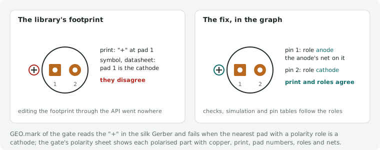
The gate's polarity sheet – one tile per polarised part with copper, silkscreen, pad numbers, roles and nets – makes this visible at a glance. GEO.mark of the gate finds it on its own: it reads the "+" the footprint draws in the silk Gerber and fails when the nearest pad with a polarity role is a cathode (the gate's stages, 8.1).
Library symbols are not always right either – and a schematic is drawn from the symbol, whatever the parts entry
says. Writing the parts library (4.1) from the datasheets turned up six whose EasyEDA symbol differs from the
manufacturer's datasheet, written up for EasyEDA and LCSC in upstream/issue-6-easyeda-symbols.md:
- the WS2812B-V5/W (C2874885) numbers DIN 3 like VSS, so a schematic puts the data input on ground and leaves pad 4 open;
- the XC6206P332MR-G (C5446) names pin 2 Vin and pin 3 Vout, Torex the other way round – the regulator fed backwards;
- the DRV8825PWPR (C81582) numbers its exposed pad 28 like GND and has no pin for pad 29, the PowerPAD;
- the Raspberry Pi Pico 2 (C41407547) numbers the test pads TP2–TP6 like pins 2–6 and swaps SWCLK and SWDIO;
- the 6N138S-TA1-L (C22451885) names the LED's anode "2" and its cathode "NC";
- the AQY212GS (C719745) has three pins for four pads.
edakit part import caches the symbol with the numbers it gives twice, and STRUCT.entry compares it: names and
numbers with the graph's pins as before, and – grade symbol, an error – a number given to two pins, a pad of the
footprint without a pin, a pin without a pad.
Where the parts entry follows the datasheet on purpose, symbol_differs names each such pin with the reason read from
the datasheet: {"4": "DIN is pin 4 – Worldsemi WS2812B-V5/W V6.1, pin table"}. The pin is left out of the
comparison, and a note (grade declared) tells the project that a schematic drawn from that symbol wires it otherwise
– check that schematic against the datasheet pin by pin, or take another part number whose symbol is right.
4.5 Own parts
Some parts nobody sells: a board of your own plugged onto the main board, a part from the bin that is no longer made, something made by hand. Nobody wrote a datasheet for them. For a board designed with edakit, its project is the datasheet – edakit derives the parts entry from it:
- In the board's project:
edakit part datasheet --connector J1– several connectors: repeat--connector, their pins are numbered on in that order. It writeshardware/datasheet/<name>.json, the parts entry, and<name>.md, the datasheet to read; the name is the project's unless--namegives another. Derived from the board: pins: the net on the board is the pin's name. The simulation's source ispower_in/vin, the groundground/gnd, a rail the board makespower_output/vout, an I2C linebidirectional/sdaorscl; any other pin takes the strongest type among the parts on its net (output, bidirectional, current_sink, input, analog, else passive). A resistor to a supply or to ground givespullandpull_ohm(REQ.missing, LVL.boot count them);v_max_vis the lowest limit on the net – a pin'sv_max_v, a capacitor'sv_max_v/ 1.5values: behaviourcurrent, the largest current from the connector over the board's scenarios (its DC scenarios: fault cases withinfoand transient runs are left out)limits:vin_min_v,vin_max_v– the voltage at the connector over those scenarioscompliance: RoHS, REACH and radio as the board's parts entries state them –radiolists their radios, is"none"when none transmits and every module and microcontroller of the board says"none", and is left out while one of them states nothing (PARTS.fact in the project that uses the board)
The board's simulation must pass, and exactly one of the connectors must be a source of it: the supply the board
draws from the project that uses it. edakit part datasheet without arguments renews every datasheet of the
project. Commit them – a datasheet belongs to a state of the board, and SYNC.source says when it is older.
2. In the project that uses the board: edakit part own ../board copies the datasheet into the parts database
and adds where it comes from: the path, the commit, the repository, and the gate run that released this state of
the board if there is one and it was neither superseded nor withdrawn (<reports>/*/fab/manifest.json of the
board's project, 8.3). The component names it like a part bought elsewhere – "part": "<name>", "bom": false
(JLCPCB does not have it), the pins as in the entry – and gets an easyeda_device: a symbol with these pin names
and the board's footprint, from your EasyEDA library.
3. Sign it off like any part (4.3), against the datasheet at that commit. Copying the same state again keeps the
sign-off; a changed board needs a new one.
The checks then treat the board like any IC: its pins take part in LIM.v, LVL and REQ, the simulation draws its
current from the supply pin, and LIM.range holds the voltage there inside vin_min_v … vin_max_v – the board was
simulated only in that range; give its own sim.json more if the host needs more. SYNC.source compares the copy with
its source:
| Finding | Result |
|---|---|
| the board's project changed after its datasheet | pending – renew it there, copy again |
| copied from uncommitted changes | pending – commit there, copy again |
| the board is not released at the state of its datasheet | warning – release it there and copy again, or accept the warning in the sign-off file (8.2) |
| the board's project is not there (another machine, CI) | note – the copy is not compared |
| a datasheet of this project is older than the project | pending – edakit part datasheet |
Not covered: the board's logic levels and timing – its signal pins are typed, not simulated. A board on a cable is no
part of the host's PCB: it goes into the same project as a second board (cables, 3.1), or the host's connector gets
its current as an external load (5.1).
Bought and hand-wired boards
Bought boards – an MCU module, a sensor board, a USB-C breakout – are parts with an entry like any other (kind
module, or connector for a breakout that only passes lines on), written from the seller's schematic, with
"bom": false when JLCPCB does not assemble them. Plugged or soldered onto the board (pin headers, castellated pads)
they are components of that board: the footprint is the header or pad row, the pins are the ones the board brings
out. REQ.missing:cc checks a USB-C receptacle on such a board in one of two ways:
- its CC eyes as pins of the entry – a
connectorwith the rolescc1,cc2, or amodulewhose entry saysvalues.usb_c{"cc": "none"}: REQ.missing:cc wants the two 5.1 kΩ on those pins, as parts of the graph; - its receptacle inside the board, CC lines no pins of the entry (an MCU module with USB-C on board):
values.usb_csays what the board has –rd_5k1andcontrollerpass,nonefails.
A bought board on a cable – a breakout in an enclosure wired to the board's power connector – is a board of its own that nobody makes:
[boards.usb]                 # Soldered 333011 on the cable W1 to J1 – bought, nobody draws it
title = "USB-C breakout"
bought = true                # no template, schematic, pcb or file: there is nothing to draw (10.1)
Its parts are components with "board": "usb" and "bom": false – the breakout with the eyes it brings out, and what
you solder onto it, such as the two 5.1 kΩ from CC1 and CC2 to GND; STRUCT wants bom: false on every one, nobody
assembles them. A cable joins it to your connector (cables, 3.1) with the resistance of its wires. The checks and the
simulation see it like any board: REQ.missing:cc the CC eyes, LIM.i the cable's rating (its i_max_a, from the wire's
own datasheet), and sim.json's source sits at the breakout's connector, with the cable in the path (5.1).
Nobody draws it: the gate's stages S and L/F leave it out with an information row each, the manifest, the fab hash,
the layout hash and so the layout review M-5 cover the made boards (8.1, 8.2), and the commands that make or read a
layout refuse it with one line (--board usb) or skip it. edakit order writes no BOM for it and puts its parts into
the carts and under its board, marked bought, in hand_assembly.md; edakit cost prices no PCB and no assembly for
it (8.4).
A hand-wired board – parts with no PCB of their own, wired by hand: a front panel's LEDs, footswitches, jacks and pots, a strip on a cable – has a key of its own:
[boards.panel]               # LEDs, footswitches and jacks in the lid, soldered to the wires of W2
title = "Front panel"
wired = true                 # hand-wired, no PCB of its own: no template, schematic, pcb or file (10.1)
edakit treats it as a bought board where that applies: in the graph, the checks and the simulation like any board –
its parts with "board": "panel" and "bom": false (STRUCT.board), the cables with their wires' resistance and
rating –, made by nobody: stages S and L/F, the manifest, the hashes, the layout commands, the assembler's BOM and the
PCB cost leave it out. What differs is what it is.
A bought board is one purchased assembly – a module with its own parts entry and supplier, perhaps with a few parts
soldered onto it. A hand-wired board's parts are the project's own: each in the carts from its supplier
(edakit order, PARTS.supplier for one without), listed under its board in hand_assembly.md as "hand-wired, no
PCB". bought = true on a front panel works as it did; STRUCT.board gives a note when no part of a bought board is a
module (kind or type module) and names wired = true – changing the key is the project's decision, edakit convert
does not do it. One board has one of the two keys, not both.
Built on a perfboard, a hand-wired board has a board file after all: the plan of the perfboard, [perfboard], checked
against the graph and drawn by edakit perfboard (7.9).
Without an edakit project
For a perfboard, an older board, a part from the bin, something made by hand, you are the datasheet. The skill
own-part asks for pins, supply range and current once, has what nobody knows measured, and writes the entry with
own: {"what": "pcb" | "bin" | "handmade", "notes": …}: every value with its source
("measured 2026-11-02, multimeter …, all LEDs on: 182 mA"), what is guessed as "assumption …", and the sign-off
against those notes. The checks treat it like the copy of an edakit board; SYNC.source has nothing to compare it with.
Own footprints as data
State:
edakit part buildruns the EasyEDA calls the bell's and a real project's scripts use. It ran against EasyEDA once, on the bell's T-Display in a throwaway project: the build, the copy in the PCB, a pad changed as a line of text and the reopened project held (implementation plan, live run of 3.6).
A footprint that exists only in EasyEDA – drawn in its editor, or rebuilt there by a script of the project – is not
text: the repository knows its name, pcb dump measures what was put there, and nobody can review or diff it. The
parts entry can hold it as data instead, in footprint_data beside footprint. edakit builds the project's copy from
it (edakit part build), holds the copy to it (SYNC.footprint), and a change of the footprint is a line of text. The
Christmas bell's T-Display, rebuilt today by its script tdisplay_device.py from the copy of a 2×12 female header, as
data:
"footprint": "HDR-TH_24P-P2.54-V-F-R2-C12-S2.54-2",
"footprint_data": {
 "symbol": "box",
 "origin": [0, 0],
 "pads": {
  "1": {"x": 11.43, "y": -13.97, "shape": "RECT", "w": 1.7, "h": 1.7, "hole": [1.1, 1.1]},
  "2": {"x": 11.43, "y": -11.43, "shape": "ELLIPSE", "w": 1.7, "h": 1.7, "hole": [1.1, 1.1]},
  …
  "24": {"x": -11.43, "y": 13.97, "shape": "ELLIPSE", "w": 1.7, "h": 1.7, "hole": [1.1, 1.1]}
 },
 "lines": [{"points": [[-12.83, -30.2], [12.83, -30.2], [12.83, 21.9], [-12.83, 21.9], [-12.83, -30.2]],
            "width": 0.1524},
           {"points": [[-4.6, -29.9], [4.6, -29.9], [4.6, -27.9], [-4.6, -27.9], [-4.6, -29.9]], "width": 0.1524}],
 "texts": [{"text": "USB", "x": 0, "y": -25.8, "size": 1.5, "width": 0.1524},
           {"text": "T-Display", "x": 0, "y": 18.3, "size": 1.5, "width": 0.1524}],
 "outline": [[-12.83, -30.2], [12.83, -30.2], [12.83, 21.9], [-12.83, 21.9]]
}
The right row is 1–12, the left row 13–24 at x = −11.43, pitch 2.54 mm, square pads 1 and 13 at the USB end. Lengths
in mm, y up, the footprint seen from the top at 0° – the axes of pcb dump (which measures in mil) and of the library
footprints edakit part import caches:
| Field | Content |
|---|---|
origin |
optional, [x, y]: where the footprint's origin lies in these coordinates – the point [place] positions and pcb dump measures from; default [0, 0]. Lets pads be written as a datasheet dimensions them (pin 1 at 0, 0) and the origin put elsewhere |
pads |
pad number → x, y, shape (RECT, ELLIPSE, OVAL), w, h, rot (degrees, default 0), layer (TOP, BOTTOM, MULTI; default MULTI with a hole, TOP without), hole [w, l] (a slot when l > w), plated (default true), mechanical (true on a pad whose number is no pin of the entry: a mounting pad) – the form part import caches pads in, in mm |
pads_same_number |
optional: number → every pad of a number used several times (shell legs), as the cache has them; pads holds the first |
lines |
silkscreen polylines {points, width}, closed when the last point is the first; width default 0.15 mm (JLCPCB prints nothing thinner) |
texts |
silkscreen texts {text, x, y, size, width, rot}, centred on x, y |
marks |
polarity marks {sign, x, y, size, width}: a "+" drawn as two strokes of size – as GEO.mark finds a "+" in the silk Gerber (strokes of 0.3 to 2 mm) –, a "−" as one |
outline |
the body on the component-shape layer, [[x, y], …]: the part's extent in EasyEDA |
symbol |
"box": the copy's symbol is rebuilt too (below); without it the carrier's symbol stays |
Why beside footprint, not in it. footprint stays the name of the copy in EasyEDA: SYNC.footprint compares it
with the PCB, part import writes and compares it, pcb plan, GEO.hole and part diff find the library footprint by
it, and the copy keeps the carrier's footprint name (the bell's T-Display is still HDR-TH_24P-…, decision D-13 there).
An object in its place would break every reader of the name – and every older edakit that reads the entry. Beside it,
an entry without footprint_data is what it was, and no project changes until it adds the data. The name says which
copy, the data what it looks like.
The symbol follows from pins and symbol, as edakit schematic draw draws a box (6.5): every pin of the entry
on the side symbol names (the others on the right), 10 units of 10 mil long, its name and number from the entry, the
body as wide as the names need. Nothing is missing for such a box. The designator prefix (U, J …) and the device's
other properties stay the carrier's.
What the entry does not have is any other drawing: a diode, an LED or a transistor is a shape schematic draw makes
up, not data. So "symbol": "box" is for modules, ICs and boards; for every other part the carrier's symbol stays,
and its pins must be the entry's (STRUCT.entry against the library symbol, SYNC.schematic in the gate). With
"symbol": "box" STRUCT.entry does not compare the graph with the carrier's library symbol: it is not the copy's.
Building the copy
- A library footprint becomes an own one:
edakit part footprint KEYshows the footprint as data,--writeputs it into the entry asfootprint_data(with a line insources); an entry that has the data is refused. The source is the dump of a placed part (<board>.geometry.json,--boardpicks the board), else the library footprint ofedakit part import.
The dump measures places and holes – shapes and sizes only of parts that have footprint data, and older dumps not
even holes –, so shape and size come from the library footprint where it has the pad at the same place; what is
still missing, PARTS.footprint names ("pads 1–24: shape missing"), exit 2. Neither the dump nor the cache has the
print: without lines, texts, marks and outline the build keeps the copy's print, with any of them the
copy's print is exactly the data's.
2. Change the data – a pad is a line. The circuit hash changes (the parts file, byte for byte), so M-1, which
checks polarity at the footprint, is done again (decision 5 of design-as-text), and the layout hash, so a sign-off of
scope layout lapses; the fab hash sees the copper at the next gate run.
3. Build the copy: edakit part build KEY checks the data (PARTS.footprint) and shows what it would build –
24 pads (24 with a hole), 2 lines, 2 texts, outline, symbol: a box with 24 pins; --write builds it in
EasyEDA, under the claim (--board picks the board; default the only made one).
The carrier is the device the part is placed with – its LCSC number, which for a stand-in is another part's (the
bell's T-Display on the female header C18722937), or its easyeda_device – and must be on the board's template
once (edakit schematic create): a device created through the API cannot be placed in the local client, the copy
of a system part can.
edakit finds the carrier's copies there, opens the footprint copy in its editor, deletes its pads – and, where the
data has print, the silkscreen, component-shape, marking and pin-soldering layers –, creates the data's, saves and
reads the pads back; with "symbol": "box" the same for the symbol. Then it saves the project. With [scripts]
the build is recorded like an easyeda script: project-library:<b> changed, the parts in the PCB and the routing
from before it (project scripts, 8.6).
4. Into the PCB: placed parts keep their old copy (9.4) – delete them in the PCB, edakit pcb parts --write,
edakit pcb dump (it measures the pads of parts with footprint data with shape, size, rotation and layer), then
edakit check: SYNC.footprint holds the copy to the data. Then the round as usual, through route all. After the
first build of a copy, edakit schematic create --save and edakit schematic layout --save come before
pcb parts: in the live run of 3.6 EasyEDA could not place the rebuilt copy ("Cannot convert undefined or null to
object") while the schematic's parts still carried the carrier – pcb parts names that way when EasyEDA answers
so.
Footprint checks
These rule checks (3.3) run only in a project where a parts entry has footprint_data – every other project runs the
checks it ran.
PARTS.footprint: the data is complete and consistent – every pad its place, shape and size, a through-hole pad
its hole; every pad a pin of the entry or mechanical, every pin a pad; lines, texts, marks and outline well formed; a
"+" mark nearest to a pad whose role is anode, plus or vbus, a "−" to cathode or minus (GEO.mark's test, on the
text); a symbol box whose sides name pins of the entry, each once.
SYNC.footprint: the copy equals the data – the footprint the dump measured on the board has the footprint name of
the entry and the data's pads: the same numbers, each within 0.02 mm of its place (SYNC.plan's tolerance; the bell's
copy lies 0.0013 mm off), the same hole within 0.01 mm, and where the dump measured them shape, size, rotation and
layer. SYNC.footprint runs on the dump, offline: in every edakit check, right after the dump of a round, where a
stale copy is found before anything is routed on it, and in the gate's stage P.
Stage L does not repeat it: there SYNC.footprint holds the PCB's pads to the same dump within 0.05 mm – data = dump in
SYNC.footprint, dump = PCB in SYNC.footprint –, and the PCB export has no holes and shapes, the dump has. The print is
not measured by pcb dump; the gate sees it on the silkscreen (GEO.mark, GEO.silk).
Until the dump has the part, pcb plan, pcb place, GEO.hole and part diff take the data as the part's geometry
("footprint data", before the library footprint), so holes and leads are checked on the text already.
Not covered yet: pad shapes NGON and POLYGON (written as RECT, ELLIPSE or OVAL), arcs and circles in the print (written as points), and the print in SYNC.footprint. A slot is built along the pad's longer side, as the live run of step 3.6 showed.
4.6 Datasheets kept with the project
edakit part fetch <key> downloads the datasheet of a parts entry once and keeps it – every later reader, the
sign-off, the second check M-1, a review, reads the same file. edakit part fetch --all fetches every entry that has
none yet. The sources, in this order:
--url URL- the entry's
datasheet.url - for an LCSC number,
pdfUrlof LCSC's product data (https://wmsc.lcsc.com/ftps/wm/product/detail?productCode=…) dataManualUrlof exactly that number in JLCPCB's catalogue (the endpoint of PARTS.stock) – where that is LCSC's datasheet page (www.lcsc.com/datasheet/lcsc_datasheet_<name>.pdf), the file behind it (wmsc.lcsc.com/wmsc/upload/file/pdf/v2/lcsc/<name>.pdf): the page is a page of the shop since 2026, the file sends the browser on to the PDF
A page is followed once, to the part's PDF: where it sends the browser by script or meta refresh (LCSC's file), else
its embedded viewer (the iframe of an item.szlcsc.com page), else a link whose address or words name the part –
its mpn or LCSC number – or say datasheet (the download of a JLCPCB part page). Its other PDF links are named, not
followed: the shop page links nothing but the certificates in its footer, and the first of them was once kept as the
datasheet of a battery holder (chapter 17).
Only a complete PDF counts – it starts with %PDF and has its %%EOF in the last 64 kB (some tools append metadata
after it). A refused request, an HTML page, a download that broke off or an expired signed link is reported with its
reason, and an earlier copy stays as it is ("kept the copy of 2026-10-27", exit 2).
The copy goes to <datasheets>/<key>.pdf ([project] datasheets, default <artifacts>/datasheets: not versioned; a
folder in the repository keeps them with the project) and its record to <key>.json: key, mpn, url (the source's
address), pdf_url (the link a page led to), source, sha256, fetched, bytes, pages, text and names_mpn.
The parts entry is not touched – a change there renews the circuit hash and lapses the sign-offs (4.3). A sign-off
records the hash it read as verified.datasheet_sha256; a new download with another hash is a warning, "changed
since the sign-off".
With pdftotext (poppler-utils) on PATH the text is checked; edakit doctor says whether it is there:
| The text | Result |
|---|---|
names the mpn as a whole word (case ignored) |
ok, names_mpn: "yes" |
| does not name it | note, "no" – some vendors never print it (the KT-0805G sheet says only "0805"); compare package, drawing and values |
| names it only inside a longer part number | warning, the variant: "MT3608L" for MT3608 – a sheet of another part (pin 6 OC instead of NC) |
| has no text layer (fewer than 20 characters a page) | note, text: false: scanned, read the drawings as images (pdftoppm -r 300 -png) |
| no pdftotext | note, text: null – nothing checked |