19 Verification and validation: how edakit is tested
For anyone who wants to know how far a finding or a clean check can be trusted, and for anyone who adds a reference circuit or an open design. After this chapter you know what edakit's tests prove and what they do not, which circuits they run on and why these, and what a new circuit must bring. How a change to edakit gets onto main is on Working on edakit.
19.1 What the testing proves
A clean edakit check says one thing: no rule edakit knows fires on your graph with the facts your parts entries
give. It does not say that the board works. Three limits stand between the two.
- A rule needs facts. A part without thresholds or ratings is not checked against them.
edakit check
   --coverage
lists what went unchecked for lack of data (rule checks, 3.3). - A rule is as good as the circuits it was tried on. Every code fires on a fault built for it, and published designs show where a rule judges a real circuit wrong. A known gap is such a wrong judgement, found and not yet fixed (19.5).
- What no rule covers is not found.
edakit mutatebuilds mistakes into a copy of your design and lists those no code reports (from a finding to a rule, 14.4).
The simulation proves what its scenarios cover: the supply voltages, loads and corners that sim.json names
(scenarios, 5.2). The regulatory review (chapter 15) is support, not legal advice: no test here guarantees anything
legally.
19.2 The layers
Two questions, and the tests split along them. Verification asks whether edakit does what its rules say: a rule fires on its fault and on nothing else. Validation asks whether the rules fit real circuits and whether edakit helps a maker: no false alarm on a published design, a task done by the assistant with the plugin.
| Layer | What it proves | Kind | Where |
|---|---|---|---|
| Engine tests | every relation fires on its fault and on nothing else, on small circuits made for the test | verification | tests/test_engines.py |
| Seen red once | every check fires on a fault built into a copy of the example led-bar; the repaired copy is clean | verification | tests/test_checks.py, test_sim*.py, test_gate.py, test_fab_run.py and more |
| Reference circuits | one circuit per domain passes clean; each seeded fault raises exactly its codes | verification | tests/reference.py, tests/test_reference.py |
| Documentation | what the walkthroughs and the quickstart quote still holds; every section a skill names exists | verification | tests/test_walkthrough*.py, test_quickstart.py, test_references.py, test_style.py |
| Wrong judgements | each false alarm once found stays fixed: the circuit it was wrong on stays quiet, the one it is right on still raises it | validation | tests/test_false_alarms.py, test_wrong_judgements.py, test_open_design_fixes.py |
| Open designs | published designs, every finding judged | validation | tests/open_designs/, tests/test_open_designs.py |
| Mutation sweep | which mistakes no code catches | validation | edakit mutate, tests/test_mutate.py |
| Live runs | KiCad reads what edakit writes; the cart at the makers; EasyEDA end to end | validation | the CI job kicad, tests/fixtures/makers/LIVE.md |
| Evals | the assistant with the plugin finds a fault, reports the coverage, adds a part | validation | evals/ |
Where they run
Every push and pull request runs the job test: all of tests/, with ngspice for the simulation. The job kicad
runs the KiCad tests in KiCad's container. Both must pass before a change reaches main.
You can run the same tests on your machine:
uv run --group dev pytest -q
The simulation's tests need ngspice installed. The evals run with claude plugin eval and cost
tokens (evals). The live runs need accounts at EasyEDA and the makers. The run of a new rule on
edakit's own boards – the Christmas bell and
pytree – reads repositories outside this one. These three you cannot repeat from the
repository alone.
The numbers
- Reference circuits: 7, with 15 seeded faults that raise 8 codes:
LIM.i,LIM.p,LIM.range,PATH.reverse,REQ.forbidden,REQ.missing,REQ.value,SIM.response. - Domains without a reference circuit:
mains,radio. - Open designs: 10, with 178 findings judged – 81 real, 72 lacks, 23 criterion, 2 known gap; 37 false alarms fixed.
19.3 The example led-bar
tests/fixtures/led-bar is the project every fault is built into. A Raspberry Pi Pico 2 drives eight LEDs through a
TLC5916 constant-current sink. 5 V come in through a JST PH connector and a Schottky diode against reverse polarity;
one button goes to ground. Its README lists the files.
It is a fixture of its own for three reasons:
- It has what most checks need. A microcontroller with its pin facts, a driver IC, a connector, a reverse diode, a button – each a place a fault can go.
- It ran through both tool chains once. Its placement plan fits the real footprints of its parts, so the layout checks have real geometry.
- It stays clean.
test_example_is_cleanholds it so. A fault goes into a copy, never into the fixture.
The walkthrough examples belong to their chapters (17, 18), and the tests hold them to what those chapters quote.
19.4 The reference circuits
edakit's own circuits, one per domain. Each is a function of tests/reference.py that adds the domain's circuit to a
copy of led-bar: its parts from 20 up, a block of its own in the drawing. They are shaped after common maker designs,
not copied from published ones.
They are synthetic on purpose. A seeded fault must raise exactly its codes, and that needs a circuit that is clean
without it. So the values are chosen for the test. Where the block library has no checked entry, a test entry stands
in: numbered C9100001 and up, marked verified.by = "reference circuit", its source "values for the reference
circuit, not from a datasheet". Never order one of them.
tests/test_reference.py holds three things. Each circuit passes edakit check and the simulation clean under its
domains, which the graph switches on by itself. Each seeded fault raises exactly its codes and no other – the overlap
test. Every domain has a circuit, but for two:
- radio has no circuit of its own: its rules are a transmitter's facts. The ESP32-DevKitC of 19.5 stands in.
- mains is recognised, not checked: spacing and isolation stay unchecked (domains, 14.2). Its one fault is built
into the example by
tests/test_hazardous.py; the ESPurna-H of 19.5 brings it onto a real board.
To look at one as a project, with or without its fault:
python tests/reference.py /tmp/ref guitar "a bias of 470 kΩ"
The catalog draws each on a page of its own with its faults. The circuits, from tests/reference.py:
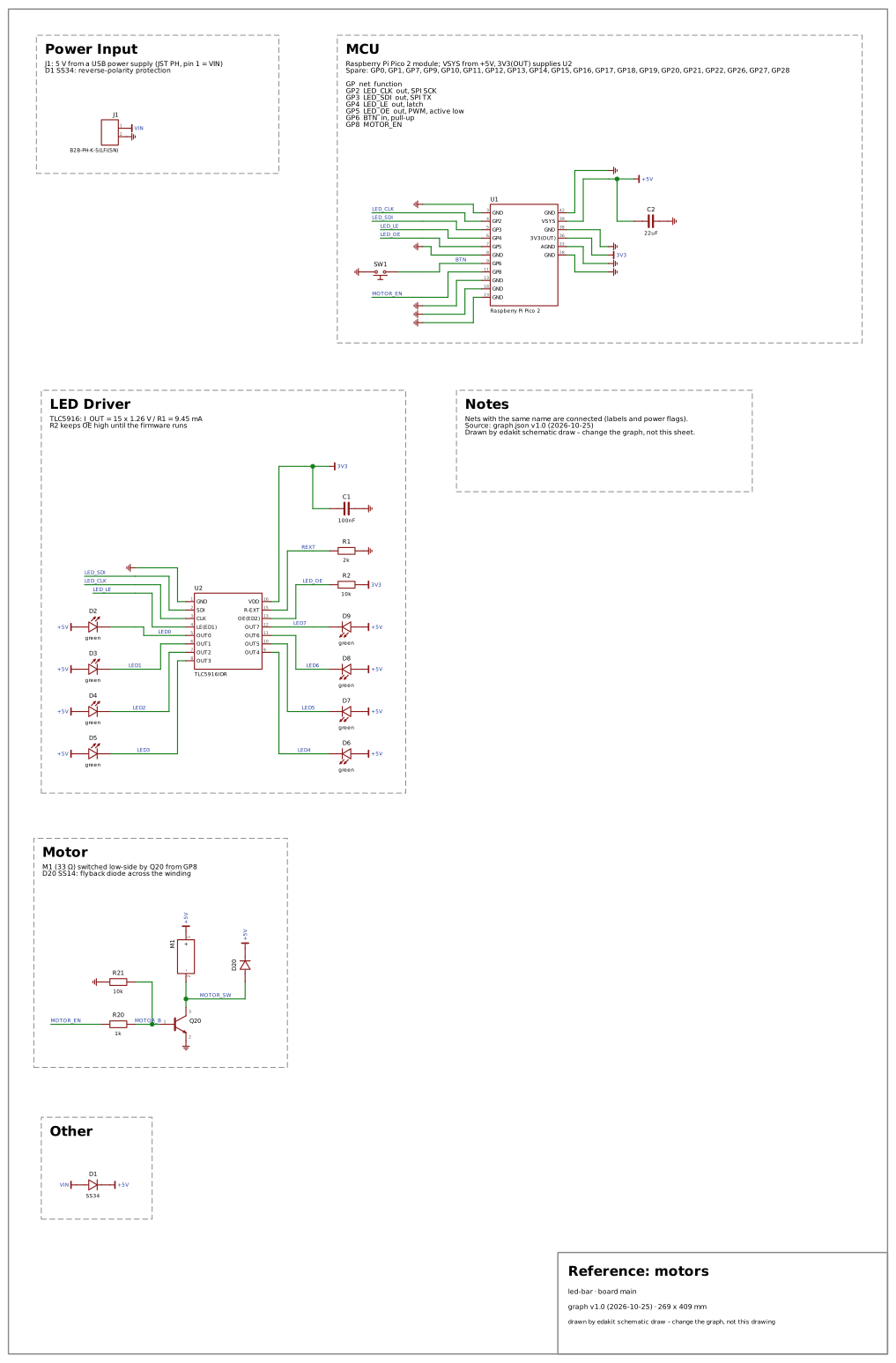 motors – domain
motors · drawing and faults
M1 (33 Ω winding) from +5V to the collector of an S8050 Q20, 1 kΩ from GP8 to the base, 10 kΩ base to emitter; an SS14 across the winding.
Why: A small motor switched low-side by a transistor is the motor circuit makers build first. The domain exists for what it needs: a flyback diode across the winding and a transistor that carries the winding's current.
- no flyback diode →
REQ.missing - a winding of 10 Ω →
LIM.i,LIM.p
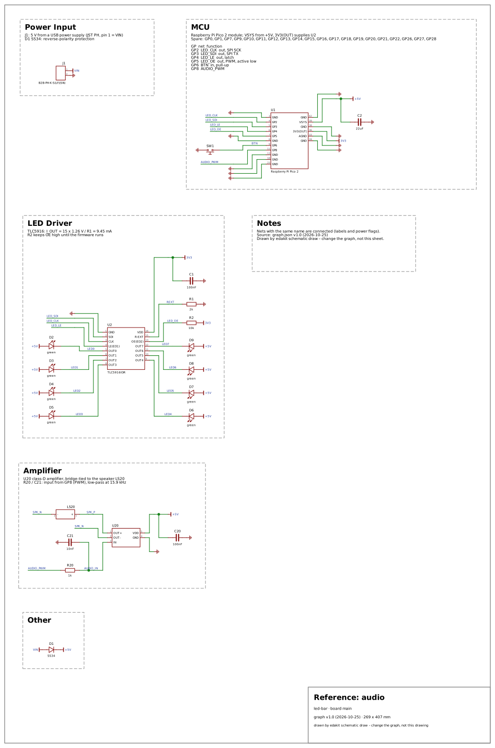 audio – domain
audio · drawing and faults
U20, a class-D amplifier on +5V with 100 nF, its bridge-tied outputs to the speaker LS20; its input from GP8 through the PWM DAC's low-pass R20 1 kΩ / C21 10 nF (C0G) – an AC run expects its corner at 15.9 kHz: flat at 1 kHz, the upper −3 dB corner between 10 and 25 kHz.
Why: A PWM pin through a low-pass into a class-D amplifier is how a microcontroller board makes sound. It holds the bridge-tied outputs, which must not touch ground, and an AC run that finds a filter corner in the wrong place.
- an output on ground →
REQ.forbidden - a filter capacitor ten times larger →
SIM.response
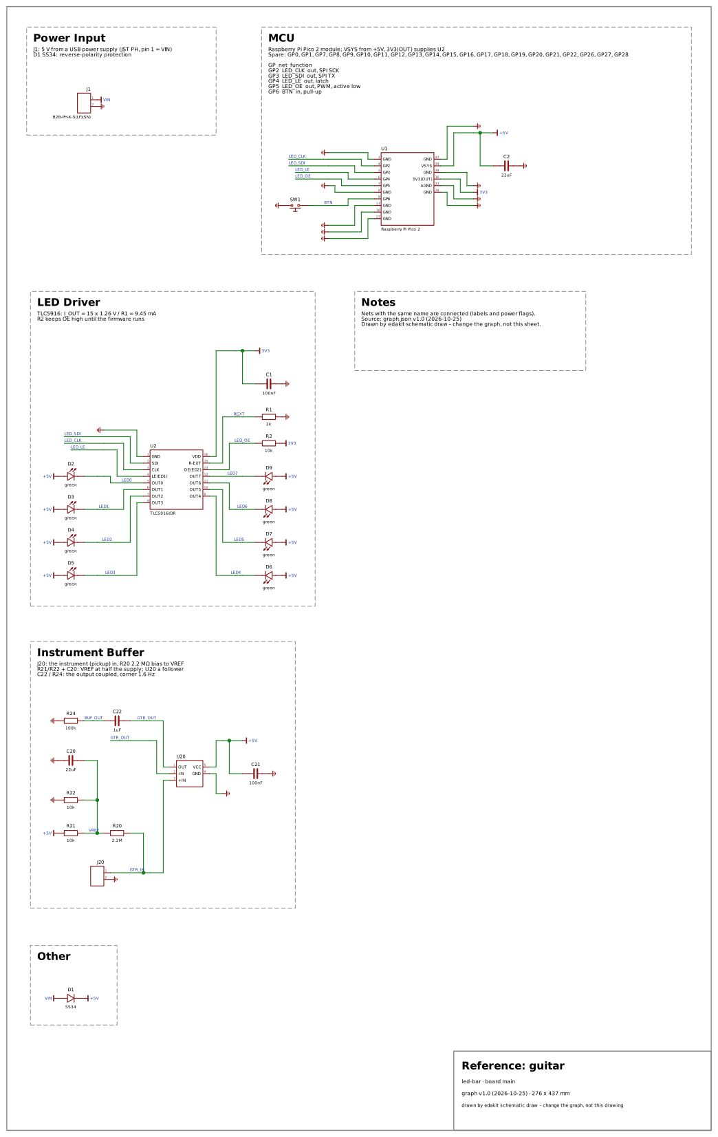 guitar – domain
guitar · drawing and faults
An instrument buffer: the jack J20's tip on GTR_IN (a pickup that wants at least 1 MΩ), 2.2 MΩ to the reference VREF (10 kΩ / 10 kΩ from +5V, 22 µF), U20 an op-amp follower on +5V with 100 nF; its output coupled through C22 1 µF (film) onto BUF_OUT with R24 100 kΩ to ground – an AC run expects the follower flat at 1 kHz and the coupling's corner, 1.6 Hz, below 10 Hz.
Why: Every pedal starts with a buffer at the instrument input. It holds the pickup's load, a reference inside the op-amp's input range, a bypass that keeps the signal's level, and the corners of the signal path in an AC run.
- a bias of 470 kΩ →
REQ.value - a reference above the inputs' range →
LIM.range - a bypass switch to an output at 0 V →
REQ.value - a coupling capacitor ten times smaller →
SIM.response
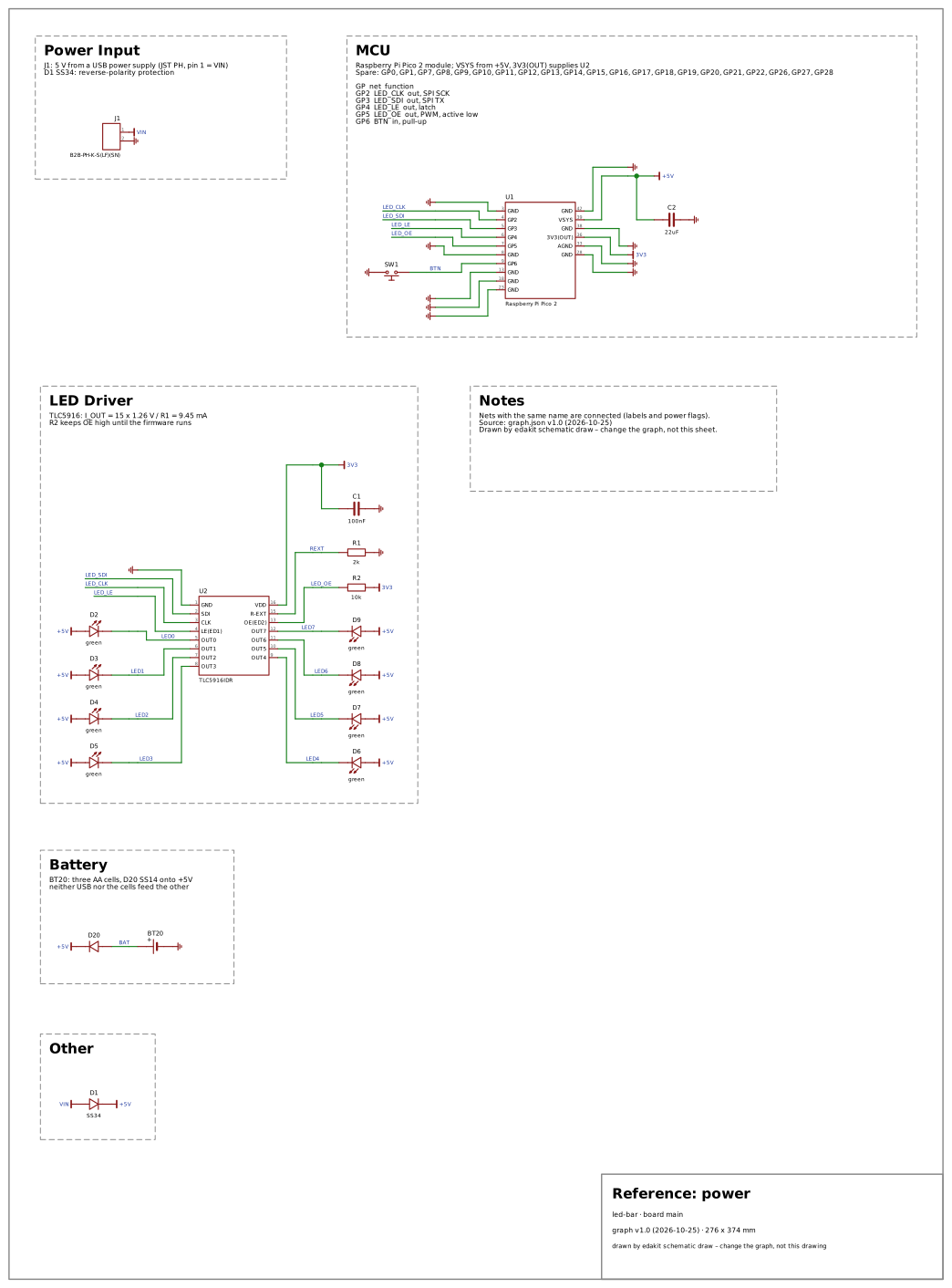 power – domain
power · drawing and faults
Three AA cells in BT20 next to USB: through an SS14 D20 onto VIN behind J1, so that neither feeds the other.
Why: Cells beside USB on one rail is a common supply of a maker board. It holds the cells' current and the diode that keeps the two sources from feeding each other.
- the cells' current limit →
LIM.i - no diode in front of the cells →
PATH.reverse
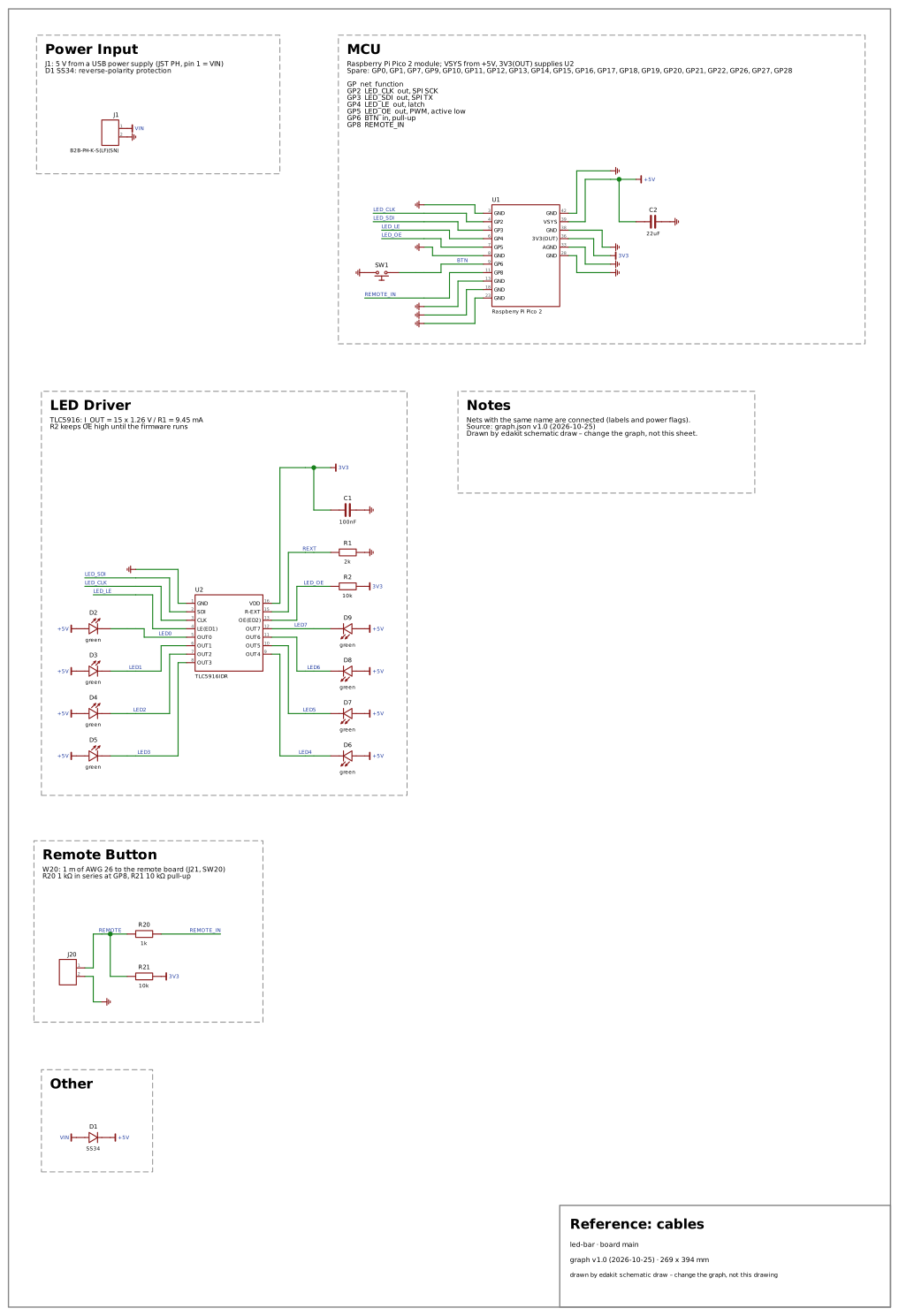 cables – domain
cables · drawing and faults
A button SW20 on a hand-wired remote board, wired by cable W20 (1 m of AWG 26) from J21 to J20 on main; on main the line reaches GP8 through 1 kΩ, with 10 kΩ to 3V3.
Why: A button at the end of a lead is the simplest line that leaves the board. It holds the series resistor that protects the pin from what the cable brings in.
- no series resistor at the pin →
REQ.missing
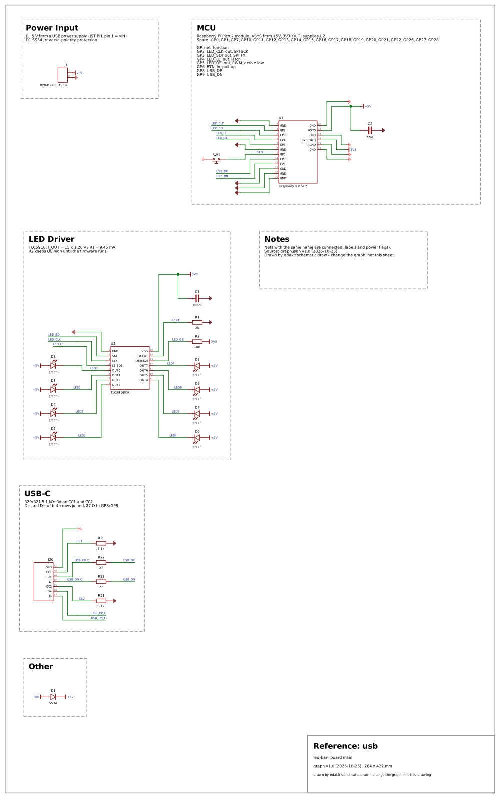 usb – domain
usb · drawing and faults
J20, a USB-C receptacle for data: 5.1 kΩ from each CC pin to GND, D+ and D− of both rows joined to GP8 and GP9 through 27 Ω.
Why: A USB-C receptacle for data is on most new boards. It holds Rd on both CC pins and D+ and D- of both rows – a board that misses one works only one way round.
- D+ of one row only →
REQ.missing - no Rd on CC2 →
REQ.missing
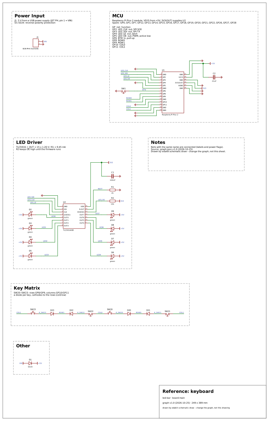 keyboard – no domain – core, on every board · drawing and faults
A 2 × 2 key matrix: SW20–SW23 from the rows (GP8, GP9) to an SS14 each, cathodes to the rows, anodes … the columns (GP10, GP11).
Why: A key matrix with a diode per key is the circuit of a keyboard. Its rules hold on every board, so it stands for no domain but core; it holds the diode per key and its direction.
- a key without its diode →
REQ.missing - a diode the wrong way round →
REQ.forbidden
19.5 The open designs
Real designs, published with their schematics, transcribed into edakit projects in tests/open_designs/. Where the
reference circuits verify, these validate. Their parts entries come from the parts' datasheets, and the design stays
as published: a fault in it is a finding, not a repair.
tests/test_open_designs.py asks that what edakit check and the simulation find on each is exactly what its
findings.toml lists, each finding judged with a reason (19.6). So a new rule that fires on one of them fails the
tests until its finding is judged: real, or a false alarm that is fixed first. Every design's README names its
source, its licence and what was changed; the README of the repository lists them under "Licence".
The designs, from their READMEs and findings.toml:
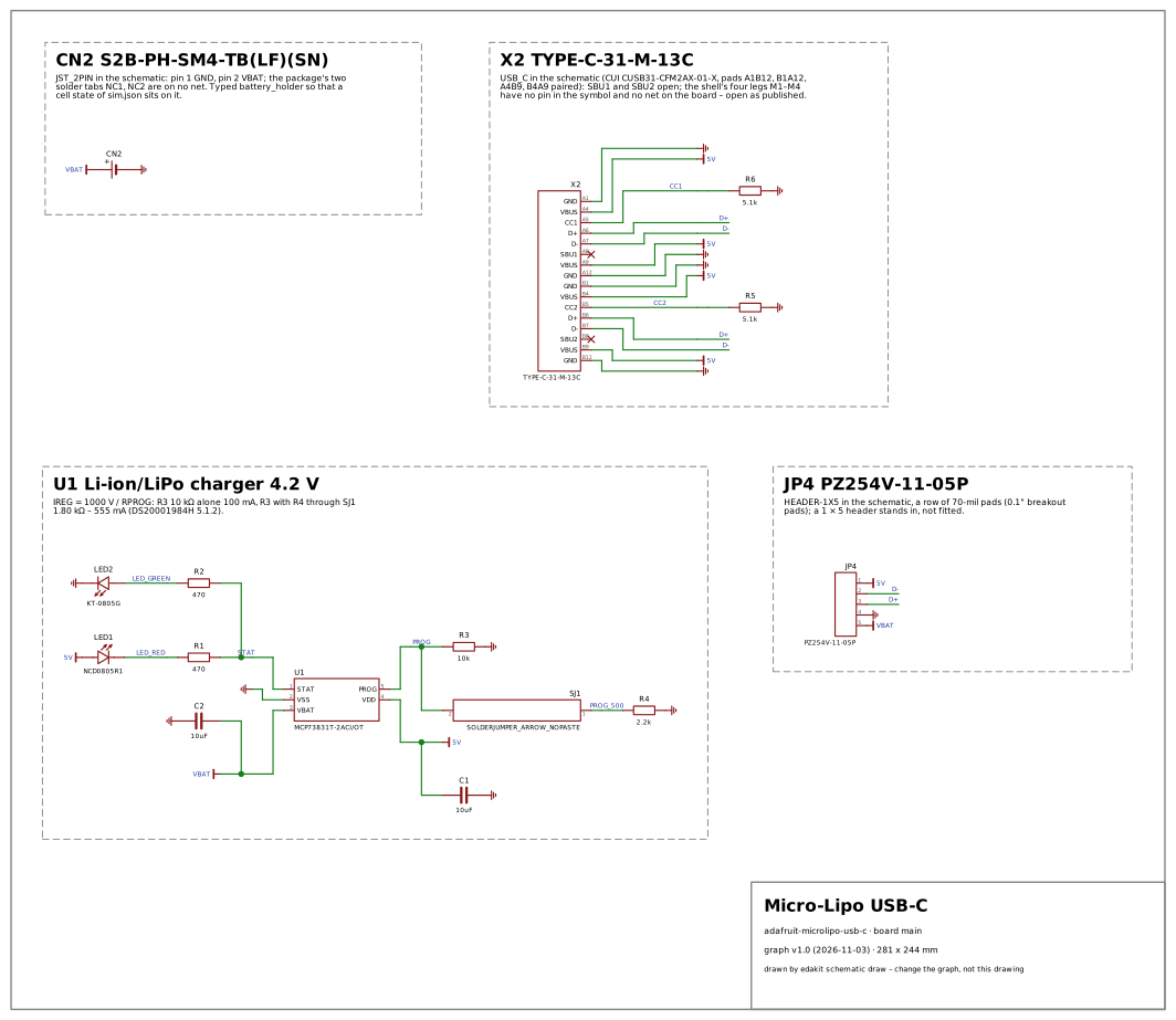 Adafruit Micro-Lipo Charger with USB Type C Jack (
adafruit-microlipo-usb-c) – CC BY-SA 3.0 · drawing and findings
Why: the first charger among edakit's test circuits – no reference circuit has one (power is three AA cells beside USB), and no other open design charges a cell. It puts a linear Li-ion charger with its behaviour model on a published board: the current R_PROG programs, held against the MCP73831's 500 mA and the cell's 1C (LIM.i/charge, LIM.backfeed into the cell), the charger's heat at a low cell (LIM.t), a second charge current set by a solder jumper, a LiPo pack whose JST plug can come reversed (PATH.reverse on a battery holder), two status LEDs on a tri-state output – the domain power with a real charger, and HINT.lithium and HINT.charge_termination on a part makers use. Makers build and copy it everywhere: the MCP73831 with a PROG resistor, two LEDs and a JST PH socket is the charger of most hobby LiPo projects – Adafruit's Micro-Lipo boards, the same circuit on Feathers and countless clones –, so a false alarm here would meet many.
Findings judged: 6 real, 11 lacks, 1 criterion; false alarms fixed: 5.
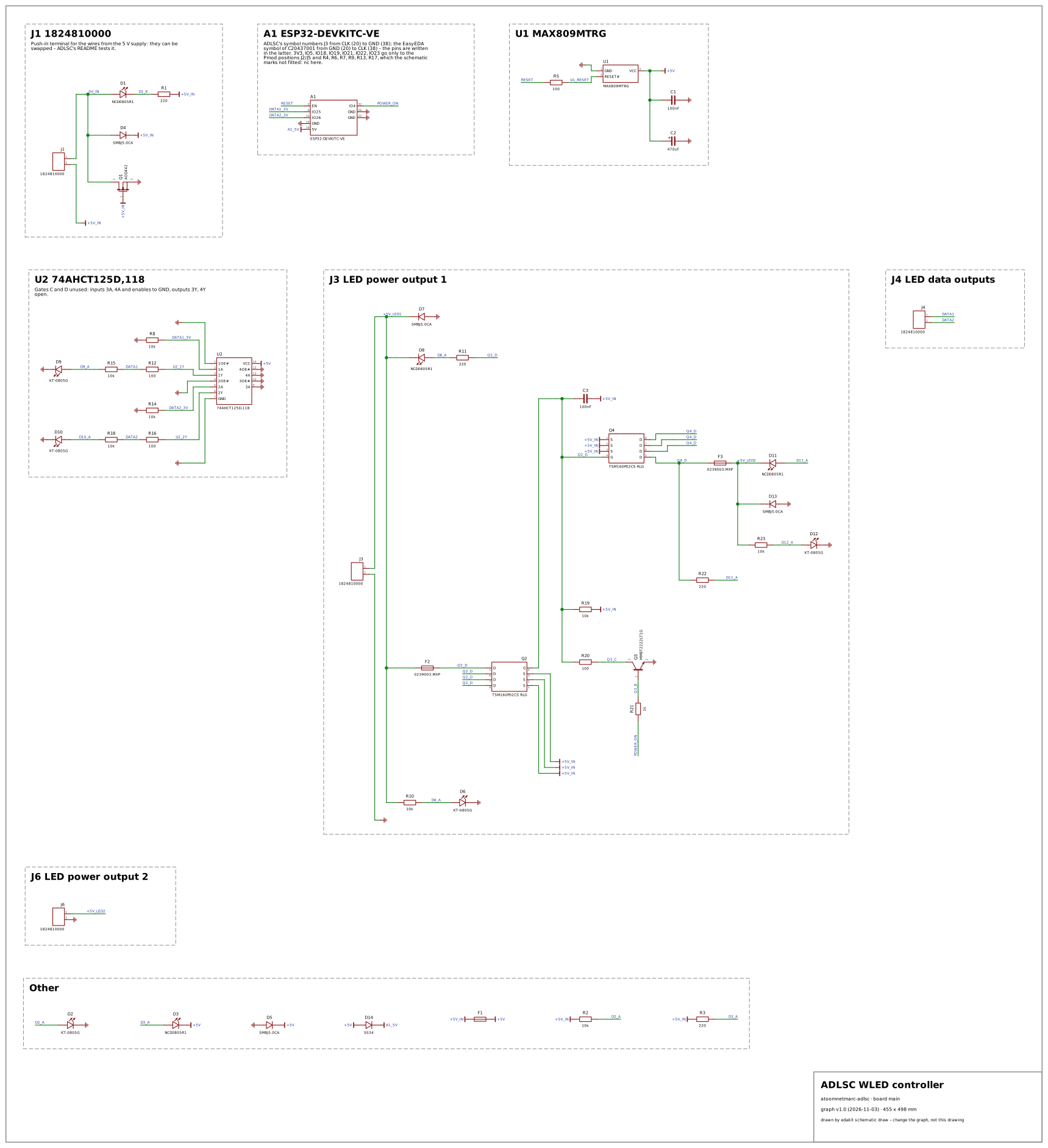 ADLSC, Atoomnet's Digital Led String Controller (
atoomnetmarc-adlsc) – Apache 2.0 · drawing and findings
Why: the WLED controller – the board makers build to drive addressable LED strips from an ESP32 at several amperes: a 5 V supply of 10 A, the ESP32's 3.3 V data shifted to 5 V by a 74AHCT125 with 100 Ω in series, the strips' power switched by the firmware and fused per output. No reference circuit has an LED-strip output, and of the open designs the Corne feeds its SK6812s one diode below 5 V to make 3.3 V data reach them and the SparkFun converter shifts levels with BSS138s; ADLSC brings the TTL-input buffer, a reverse-polarity N-MOSFET in the ground return, a voltage supervisor on the ESP32's EN, P-MOSFET high-side switches driven from a GPIO through an NPN, glass fuses with blown-fuse LEDs, a polyfuse, TVS diodes on every 5 V rail, and an ESP32 development board plugged in behind a Schottky diode – real parts with their datasheets, in a class of board that WLED's users copy, where a false alarm would meet many.
Findings judged: 9 real, 7 criterion; false alarms fixed: 3.
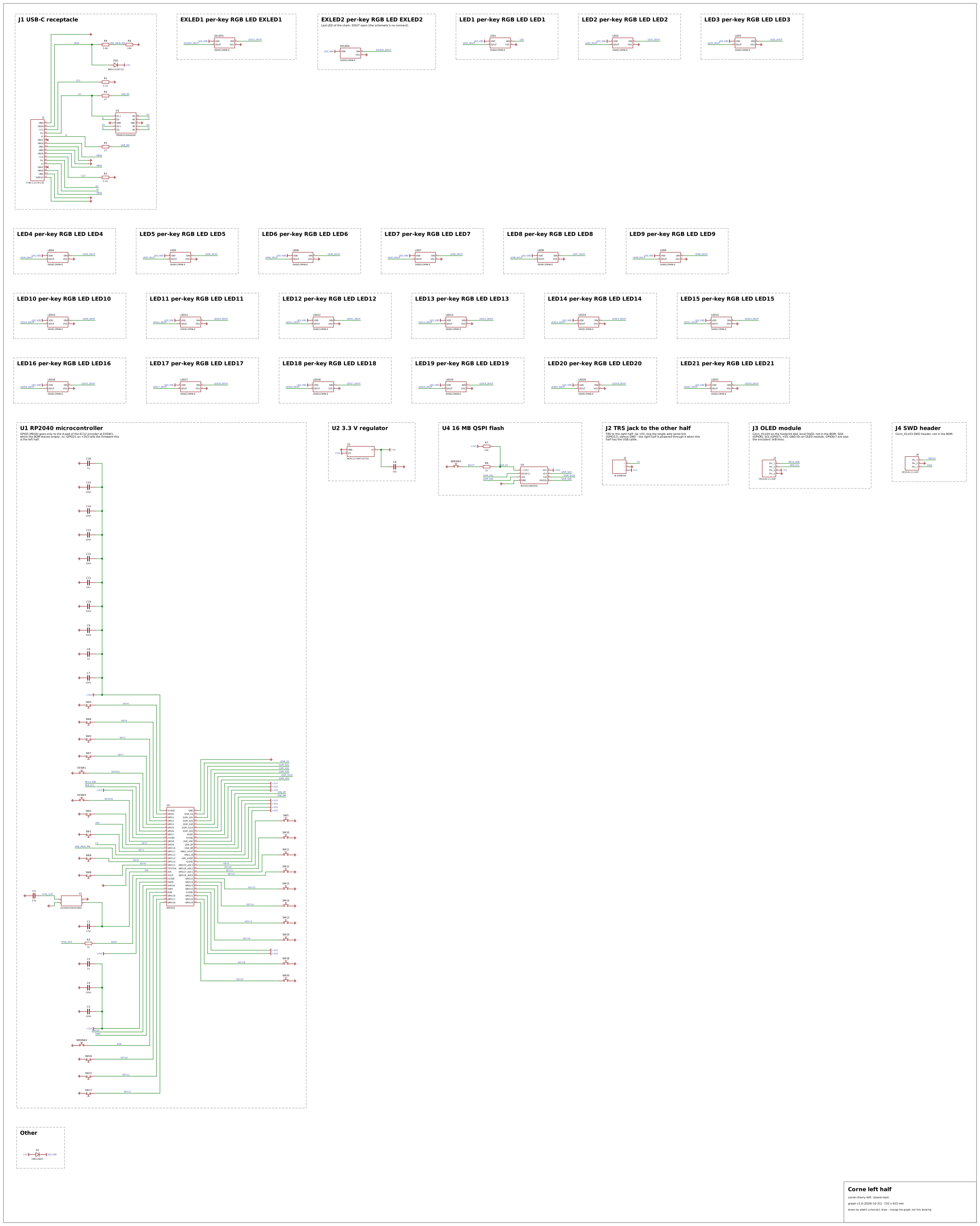 Corne keyboard v4, left half (
corne-cherry-left) – CC BY 4.0 · drawing and findings
Why: a split keyboard many makers build. Its v4 left half brings what no reference circuit has: an RP2040 with its crystal and USB-C port, 23 keys each on a GPIO of its own, and a chain of 23 SK6812MINI-E that runs one diode below 5 V while its data comes from a 3.3 V pin. It is the one LED chain on a board among the designs, and with the v3 it shows the same keyboard without and with a matrix.
Findings judged: 32 real, 4 lacks, 3 criterion; false alarms fixed: 5.
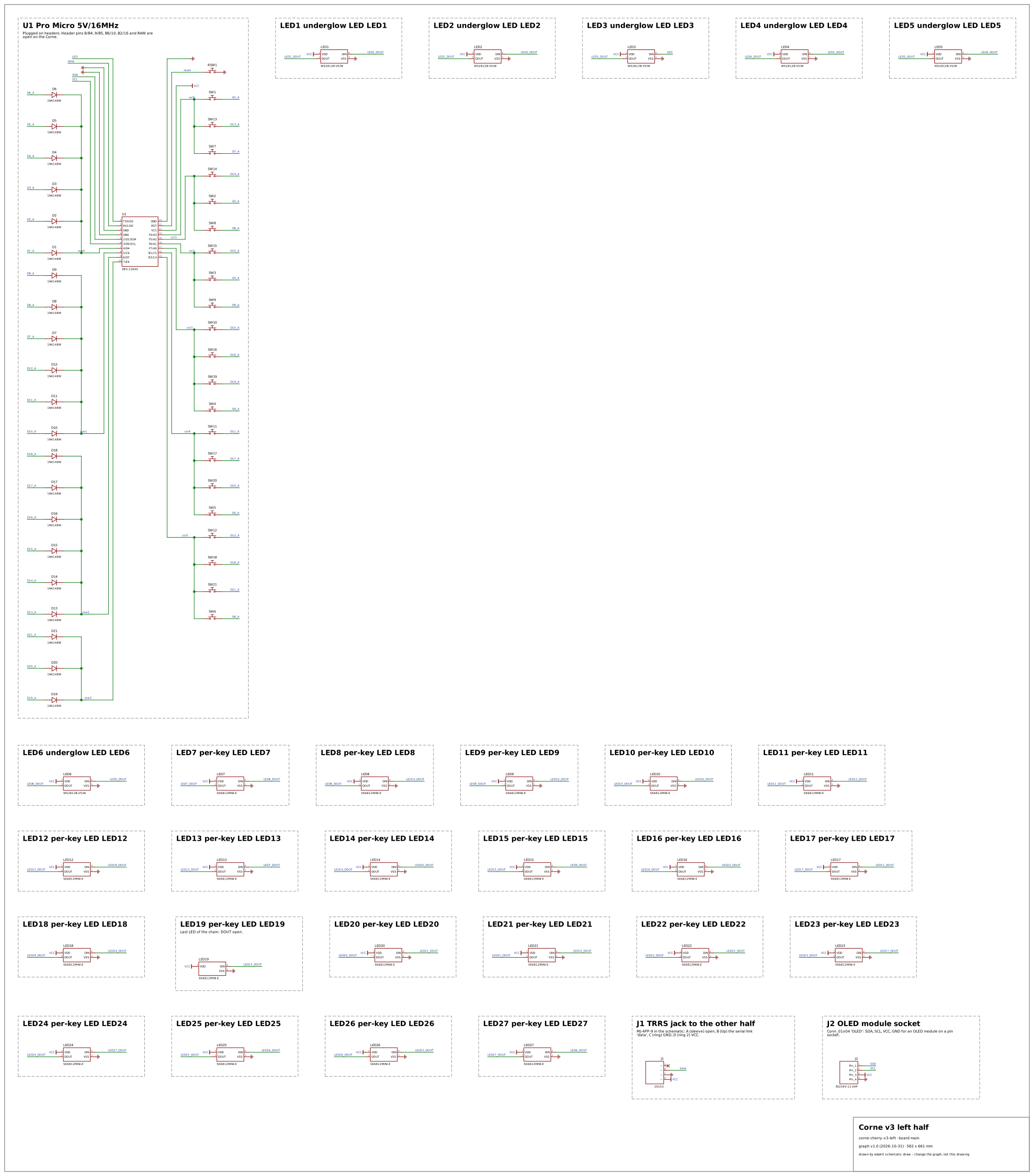 Corne Cherry keyboard v3, left half (
corne-cherry-v3-left) – MIT · drawing and findings
Why: the same keyboard as a real key matrix: 21 keys in a 4 × 6 matrix with a diode per key on a Pro Micro, where the reference circuit keyboard has 2 × 2. edakit's matrix rules and the simulated scan run on it – the scan reads through the diodes and ghosts without them.
Findings judged: 5 real, 5 lacks, 2 criterion; false alarms fixed: 2.
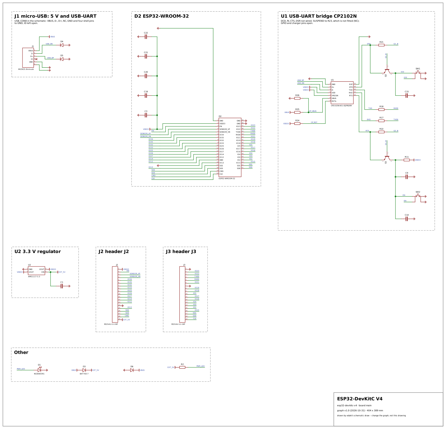 ESP32-DevKitC V4 (
esp32-devkitc-v4) – no licence stated – only the circuit's facts transcribed · drawing and findings
Why: the board many ESP32 projects start from: usb, radio and power on one board – the USB-UART bridge, the two transistors of the auto-program circuit, the 3.3 V regulator, the module's bands and e.i.r.p. The domain radio has no reference circuit; this design was the first to stand in for it.
Findings judged: 12 real, 36 lacks, 2 criterion; false alarms fixed: 6.
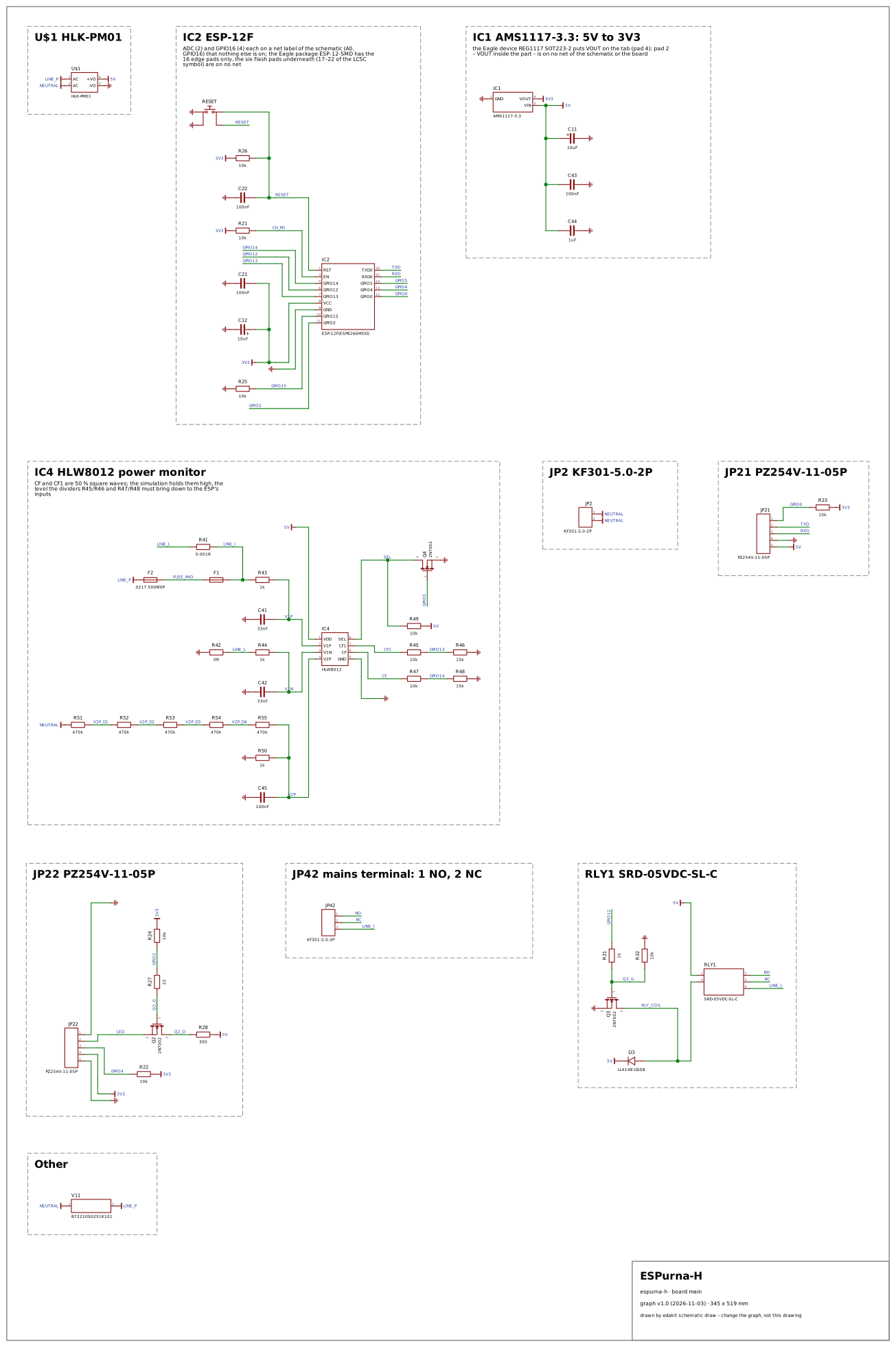 ESPurna-H (
espurna-h) – CC BY-SA 4.0 · drawing and findings
Why: the only board here with mains on it – an HLK-PM01 behind a thermal fuse, a 500 mA fuse and a varistor, a 10 A relay that switches the load, and an HLW8012 power monitor on a 1 mΩ shunt and a 5 × 470 kΩ divider from neutral, whose 0 Ω resistor ties the low-voltage ground to the line. No reference circuit (tests/reference.py has none with mains or a relay) and no other open design brings LIM.hazardous and the domain mains onto a real board, nor a relay coil driven from a 3.3 V GPIO with its flyback diode; around them sit the low-voltage checks edakit does make – the 2N7002's gate drive, the regulator, the ESP8266's levels and boot pins. An HLK-PM01, an ESP module and a relay is the common recipe of a homemade mains smart switch, and ESPurna is a widely used open firmware for such switches, so a false alarm here would meet many.
Findings judged: 13 real, 1 criterion, 1 known gap; false alarms fixed: 5.
Known gaps – each with its reason on the design's page: LIM.range at Q4.
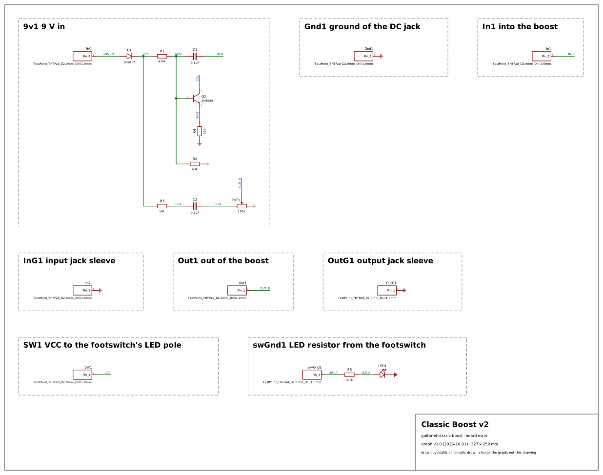 GuitarML Classic Boost v2 (
guitarml-classic-boost) – MIT · drawing and findings
Why: a one-transistor boost, the stage many builders start with. Beside it the combo's transistors are followers – their bias hardly depends on the gain. The boost is the one stage whose operating point the transistor's spread moves: a common-emitter stage, its base held by a divider, its gain set by the collector and emitter resistors – the case of FT-17's corners and of a gain an AC run can show. It also has no IC at all: nothing types its supply and ground, which showed a false alarm, fixed since (findings.toml, [[fixed]]).
Findings judged: 1 lacks, 2 criterion; false alarms fixed: 2.
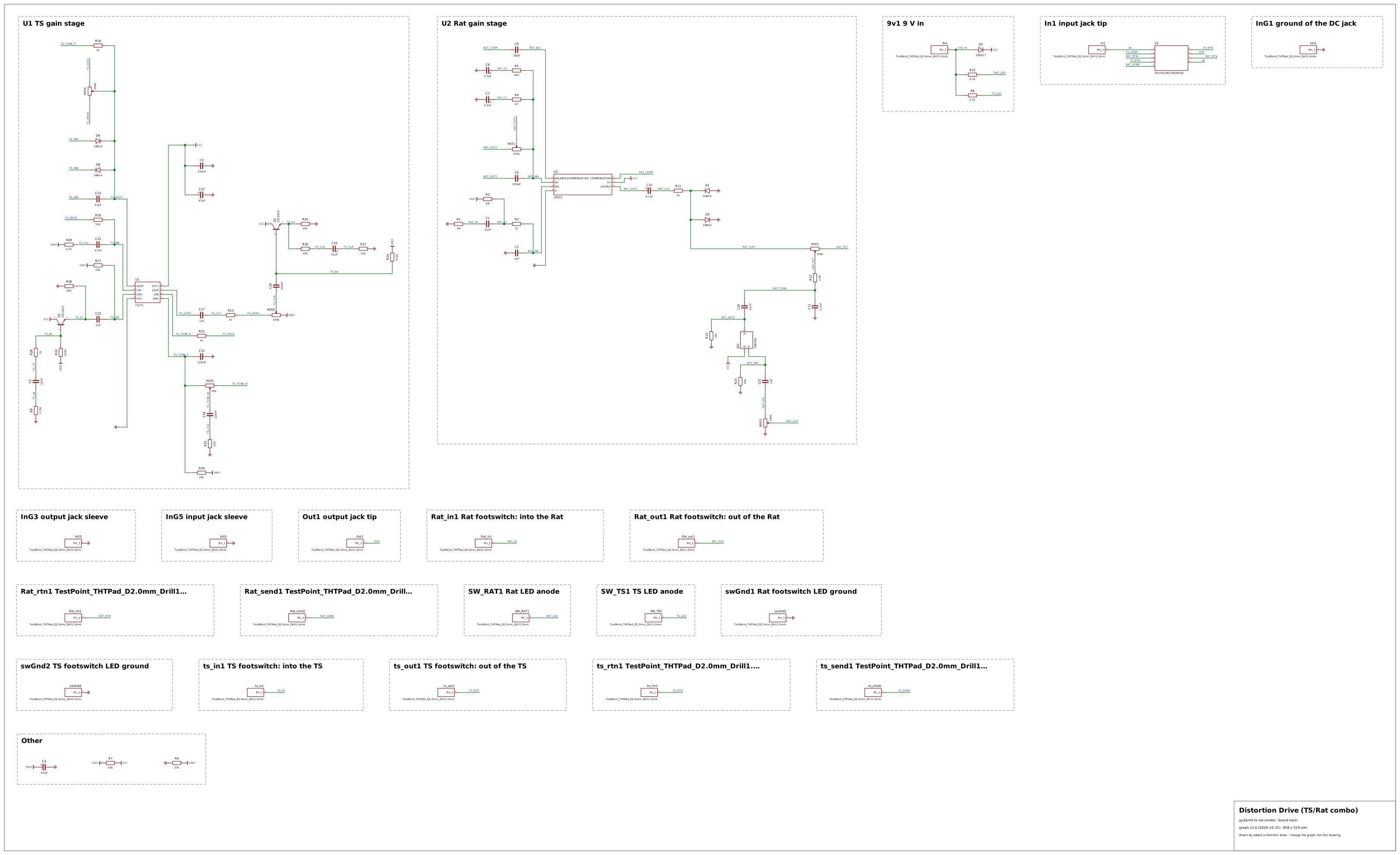 GuitarML Tubescreamer/Rat combo (
guitarml-ts-rat-combo) – MIT · drawing and findings
Why: two drive circuits makers copy often, a Tube Screamer-style and a Rat-style stage, on one board: op-amp stages biased at half the supply, BJT and JFET followers, a 3PDT switch on the board that orders the effects, and footswitches wired by hand. It brings real op-amps where the reference circuit guitar has a test entry, and a reversed electrolytic (C19) that edakit finds.
Findings judged: 2 real, 6 lacks, 3 criterion; false alarms fixed: 6.
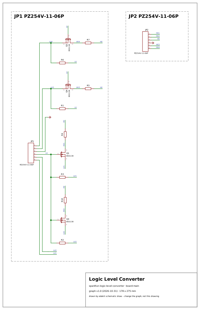 SparkFun Logic Level Converter (
sparkfun-logic-level-converter) – CC BY-SA 3.0 · drawing and findings
Why: the BSS138 level shifter sits on many maker boards that join 3.3 V and 5 V parts. It brings a circuit whose function is a level in both directions – each channel simulated, driven from either side –, which no reference circuit has, with real MOSFETs from their datasheet.
Findings judged: 6 lacks, 1 criterion, 1 known gap; false alarms fixed: 0.
Known gaps – each with its reason on the design's page: LIM.range at Q1.
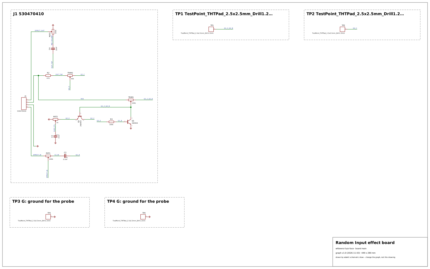 Random Input (whbeers) (
whbeers-fuzz-face) – CC0 1.0 · drawing and findings
Why: the Fuzz Face is the two-transistor circuit whose bias makers fight with: Q1's collector drives Q2's base directly and Q2's emitter feeds back to Q1's base through 100 kΩ, so the operating point rests on both transistors' gain and leakage – and they pull it in opposite directions, the case of the spread's corners per part (FT-17, handbook 5.2). No reference circuit has a direct-coupled pair, and the open designs' stages are a divider-held common emitter (the Classic Boost) and followers (the combo). This one names its bias targets on the schematic – TP2, Q2's collector, at 5.0 V, TP1 at 500–700 mV – and replaces the collector resistors with trimmers to reach them, so the simulation can hold the bias to the design's own window, show how far the spread moves it at one setting, and show the trimmers' range covering it. It is also a board without an IC, fed through a connector from another board, and its fuzz control carries DC. Makers build the Fuzz Face as one of the first fuzzes: a dozen parts, a sound tied to the transistors, and the reputation for picky bias.
Findings judged: 2 real, 3 lacks, 1 criterion; false alarms fixed: 3.
19.6 How a finding is judged
Four words judge a finding on an open design. They read the same way on your own findings.
| Judged | Means | On your board |
|---|---|---|
| real | a point of the design: the board has the fault | fix the board |
| lacks | a fact the transcription or the datasheets lack, so edakit cannot decide | add the fact to the parts entry or the graph |
| criterion | edakit's yardstick, not the design's: the design meets its need another way | accept the finding with the reason |
| known gap | edakit judges it wrong, and the fix is not built yet | accept it with the reason, and propose the fix |
An accepted finding needs its reason in the graph or the sign-off file (the catalog, 14.2). A false alarm on your
board goes back as a proposal: /edakit:propose-feature (feature proposals, 11.6). Fixed, it is held like the open
designs' false alarms – a test with the circuit it was wrong on and the one it is right on.
19.7 Adding a reference circuit or an open design
A new one has to earn its place. The rules below are what the tests hold, or what a reviewer asks where a test cannot.
A reference circuit
- A gap of its own. A domain no circuit covers, or a family of codes of a covered domain that no seeded fault raises yet. A new domain needs one: the tests fail without it.
- Built onto led-bar. One function in
REFERENCES: parts from 20 up, the microcontroller's pins it uses freed, a block of its own in the drawing, the board titled "Reference: name". - Its parts named honestly. The block library's checked entries first. A test entry only where the library lacks
one – numbered
C91000xx, marked as a reference circuit's, its source saying it is not from a datasheet. A test holds the marks. - Clean. No error, warning or pending finding, no row of the simulation that fails or warns; its domain switched on by the graph alone.
- Its faults exact. At least one seeded fault for each family of codes it is there for, each a mistake a maker makes, each raising exactly its codes. A fault only the simulation shows, where the domain has a rule of the simulation.
- Described. The function's docstring says what the circuit is, with its values; its entry in
WHYsays why this circuit stands for its domain. A test asks both; 19.4 shows them. - Small enough to read. One page in the catalog's drawing.
An open design
- Published, and the licence allows it. A schematic anyone can open, under a licence that allows an adaptation: MIT, BSD, CC BY, CC BY-SA, CERN-OHL and the like – not a non-commercial or no-derivatives one. The README names the source with its commit or revision, the licence – a Creative Commons licence with its link –, and every change. Without a stated licence, only the circuit's facts are transcribed, not the drawing.
- Something the others lack. A domain or a kind of circuit no reference circuit and no open design covers, with real parts. Preferably a design makers build and copy, so that a false alarm on it would meet many.
- Transcribed as published. Not repaired. A part the schematic does not name gets a stand-in, named in the README. Every parts entry names its datasheet and fits the schema.
- Every finding judged. In
findings.toml, each with its judgement and a reason. A false alarm is fixed and held intests/test_open_design_fixes.py, or judged a known gap with the reason. - Described. A paragraph in its README that starts with "Why this design:" and says what it brings. A test asks for it; 19.5 shows it.
The way in
From a project, a missing circuit is a feature proposal: /edakit:propose-feature (feature proposals, 11.6). In the
repository, the skill add-feature builds it, test first. Then the chapter's lists are written anew:
uv run python -m edakit.catalog.handbook --write
uv run python docs/catalog/build.py
tests/test_catalog.py and tests/test_catalog_page.py fail while either is out of date.
19.8 The evals
The tests prove the code. The evals measure whether the assistant with the plugin does a typical task: find a seeded
fault in a reference circuit, report what went unchecked, add a status LED, write the inventory of a requirements
file, or make a first circuit with the site as its only guide. Each case writes its project with
tests/reference.py into an empty workspace.
A run is graded by what the assistant printed, which commands it ran, and – where a task needs judgement – a judge model. The cases run with Sonnet and with Opus, since edakit must work with the smaller model too. One run per case is a reading, not a rate: a difference between two models counts after several runs.
The cases, how to run them and the baseline: evals.
19.9 What is not covered
- Two domains without a reference circuit. radio and mains (19.4); for mains, spacing and isolation are not checked at all.
- A low-voltage side tied to the line, beyond a terminal. edakit holds every voltage against the board's own
ground. LIM.hazardous/ground names that ground tied to a mains terminal's
lineorneutralpin – straight, through a 0 Ω bridge, a fuse, a switch, a diode or a small resistor, as on the ESPurna-H –; mains brought in otherwise (a module's pins, a terminal without those roles) or tied through anything larger stays unseen, and the low-voltage side looks safe although it is not. - The known gaps. Each listed with its design and reason (19.5).
- What no code catches.
edakit mutatenames the mistakes on led-bar no code reports (from a finding to a rule, 14.4). - The schematic and the layout in EasyEDA. Only live runs reach them; KiCad is tested in CI (what KiCad 10 confirmed, 16.8).
- A board's behaviour beyond its scenarios. The simulation checks the states
sim.jsonnames, and timing only where a transient run asks for it.